HL Paper 2
This question is in two parts. Part 1 is about energy resources. Part 2 is about transformers.
Part 2 Transformers
Modern televisions (TVs) can be left in “standby” mode so that they are available for immediate use. The internal circuits are powered at low voltage using a step-down transformer connected to the mains power supply. To prevent the TV from using any energy, the transformer must be disconnected from the mains supply.
When in “standby” mode, a TV transformer supplies a current of 0.45 A at 9.0 V to the internal circuits.
Outline the features of an ideal step-down transformer.
Real transformers are subject to energy loss. State and explain how two causes of these energy losses may be reduced by suitable features in these transformers.
1.
2.
Calculate the power consumed by the internal circuits when the TV is in “standby” mode.
The efficiency of the transformer is 0.95. Determine the current supplied by the 230 V mains supply.
The TV is on “standby” for 75% of the time. Calculate the energy wasted in one year by not switching off the TV.
\[{\text{1 year}} = 3.2 \times {10^7}{\text{ s}}\]
A negatively charged thundercloud above the Earth’s surface may be modelled by a parallel plate capacitor.
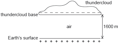
The lower plate of the capacitor is the Earth’s surface and the upper plate is the base of the thundercloud.
The following data are available.
\[\begin{array}{*{20}{l}} {{\text{Area of thundercloud base}}}&{ = 1.2 \times {{10}^8}{\text{ }}{{\text{m}}^2}} \\ {{\text{Charge on thundercloud base}}}&{ = -25{\text{ C}}} \\ {{\text{Distance of thundercloud base from Earth's surface}}}&{ = 1600{\text{ m}}} \\ {{\text{Permittivity of air}}}&{ = 8.8 \times {{10}^{ - 12}}{\text{ F }}{{\text{m}}^{ - 1}}} \end{array}\]
Lightning takes place when the capacitor discharges through the air between the thundercloud and the Earth’s surface. The time constant of the system is 32 ms. A lightning strike lasts for 18 ms.
Show that the capacitance of this arrangement is C = 6.6 × 10⁻⁷ F.
Calculate in V, the potential difference between the thundercloud and the Earth’s surface.
Calculate in J, the energy stored in the system.
Show that about –11 C of charge is delivered to the Earth’s surface.
Calculate, in A, the average current during the discharge.
State one assumption that needs to be made so that the Earth-thundercloud system may be modelled by a parallel plate capacitor.
Part 2 Power transmissions
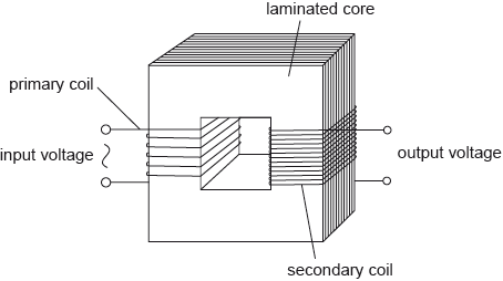
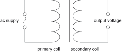
The diagram shows the main features of an ideal transformer whose primary coil is connected to a source of alternating current (ac) voltage.
A different transformer is used to transmit power to a small town.

The transmission cables from the power station to the transformer have a total resistance of 4.0 Ω. The transformer is 90% efficient and steps down the voltage to 120 V. At the time of maximum power demand the effective resistance of the town and of the cables from the transformer to the town is 60 mΩ.
Outline, with reference to electromagnetic induction, how a voltage is induced across the secondary coil.
The primary coil has 25 turns and is connected to an alternating supply with an input voltage of root mean squared (rms) value 12 V. The secondary coil has 80 turns and is not connected to an external circuit. Determine the peak voltage induced across the secondary coil.
Calculate the current in the cables connected to the town
Calculate the power supplied to the transformer.
Determine the input voltage to the transformer if the power loss in the cables from the power station is 2.0 kW.
Outline why laminating the core improves the efficiency of a transformer.
This question is about electromagnetic induction.
In order to measure the rms value of an alternating current in a cable, a small coil of wire is placed close to the cable.
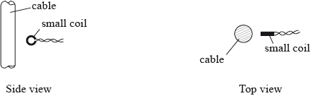
The plane of the small coil is parallel to the direction of the cable. The ends of the small coil are connected to a high resistance ac voltmeter.
Use Faraday’s law to explain why an emf is induced in the small coil.
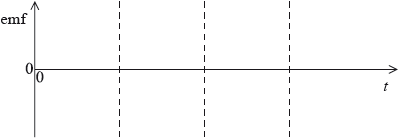
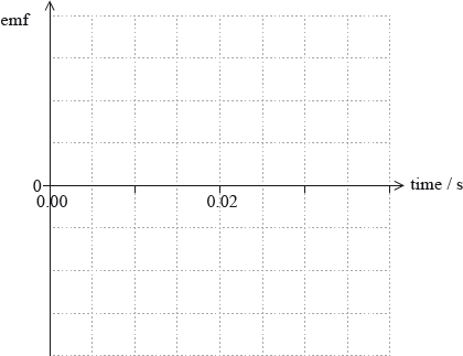
The graph below shows the variation with time \(t\) of the current in the cable.
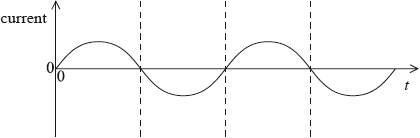
On the axes below, draw a sketch graph to show the variation with time of the emf induced in the small coil.
Explain how readings on the high resistance ac voltmeter can be used to compare the rms values of alternating currents in different cables.
A capacitor consists of two parallel square plates separated by a vacuum. The plates are 2.5 cm × 2.5 cm squares. The capacitance of the capacitor is 4.3 pF.
Calculate the distance between the plates.
The capacitor is connected to a 16 V cell as shown.
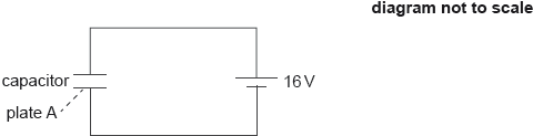
Calculate the magnitude and the sign of the charge on plate A when the capacitor is fully charged.
The capacitor is fully charged and the space between the plates is then filled with a dielectric of permittivity ε = 3.0ε0.
Explain whether the magnitude of the charge on plate A increases, decreases or stays constant.
In a different circuit, a transformer is connected to an alternating current (ac) supply.
The transformer has 100 turns in the primary coil and 1200 turns in the secondary coil. The peak value of the voltage of the ac supply is 220 V. Determine the root mean square (rms) value of the output voltage.
Describe the use of transformers in electrical power distribution.
This question is about generating emfs.
A vertical metal rod of length 0.25 m moves in a horizontal circle about a vertical axis in a uniform horizontal magnetic field.
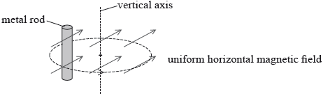
The metal rod completes one circle of radius 0.060 m in 0.020 s in the magnetic field of strength 61 mT.
Define magnetic flux.
(i) Determine the maximum emf induced between the ends of the metal rod.
(ii) Using the axes, sketch a graph to show the variation with time of the emf of the metal rod.
The diagram shows a sketch of an ideal step-down transformer.

The number of turns in the primary coil is 1800 and that in the secondary coil is 90.
State Faraday’s law of induction.
Explain, using Faraday’s law of induction, how the transformer steps down the voltage.
The input voltage is 240 V. Calculate the output voltage.
Outline how energy losses are reduced in the core of a practical transformer.
Step-up transformers are used in power stations to increase the voltage at which the electricity is transmitted. Explain why this is done.
The following data are available for a natural gas power station that has a high efficiency.
| Rate of consumption of natural gas | = 14.6 kg s–1 |
| Specific energy of natural gas | = 55.5 MJ kg–1 |
| Efficiency of electrical power generation | = 59.0 % |
| Mass of CO2 generated per kg of natural gas | = 2.75 kg |
| One year | = 3.16 × 10⁷ s |
Electrical power output is produced by several alternating current (ac) generators which use transformers to deliver energy to the national electricity grid.
The following data are available. Root mean square (rms) values are given.
| ac generator output voltage to a transformer | = 25 kV |
| ac generator output current to a transformer | = 3.9 kA |
| Transformer output voltage to the grid | = 330 kV |
| Transformer efficiency | = 96% |
(i) Calculate the current output by the transformer to the grid. Give your answer to an appropriate number of significant figures.
(ii) Electrical energy is often delivered across large distances at 330 kV. Identify the main advantage of using this very high potential difference.
In an alternating current (ac) generator, a square coil ABCD rotates in a magnetic field.

The ends of the coil are connected to slip rings and brushes. The plane of the coil is shown at the instant when it is parallel to the magnetic field. Only one coil is shown for clarity.
The following data are available.
| Dimensions of the coil | = 8.5 cm×8.5 cm |
| Number of turns on the coil | = 80 |
| Speed of edge AB | = 2.0 ms–1 |
| Uniform magnetic field strength | = 0.34 T |
(i) Explain, with reference to the diagram, how the rotation of the generator produces an electromotive force (emf ) between the brushes.
(ii) Calculate, for the position in the diagram, the magnitude of the instantaneous emf generated by a single wire between A and B of the coil.
(iii) Hence, calculate the total instantaneous peak emf between the brushes.
This question is about induced electromotive force (emf ).
A rod made of conducting material is in a region of uniform magnetic field. It is moved horizontally along two parallel conducting rails X and Y. The other ends of the rails are connected by a thin conducting wire.

The speed of the rod is constant and is also at right angles to the direction of the uniform magnetic field.
(i) Describe, with reference to the forces acting on the conduction electrons in the rod, how an emf is induced in the rod.
(ii) An induced emf is produced by a rate of change of flux. State what is meant by a rate of change of flux in this situation.
The length of the rod in (a) is 1.2 m and its speed is 6.2 m s–1. The induced emf is 15 mV.
(i) Determine the magnitude of the magnetic field strength through which the rod is moving.
(ii) Explain how Lenz’s law relates to the situation described in (a).
This question is about induced electromotive force (emf).
A loop of copper wire in a region of uniform magnetic field is rotated about a horizontal axis.
The magnitude of the magnetic field strength is B and the area of the loop is A.
(i) State the minimum value and the maximum value of the magnetic flux linking the loop.
(ii) Outline with reference to Faraday’s law why, if the speed of rotation of the loop is increased, the maximum emf induced in the loop is increased.
The loop in (a) is connected in series with a resistor of resistance 15 Ω. The root mean squared (rms) value of the sinusoidal current in the resistor is 2.3 mA.
(i) Explain what is meant by the rms value of a sinusoidal current.
(ii) Determine the maximum power dissipated in the resistor.
The electrical circuit shown is used to investigate the temperature change in a wire that is wrapped around a mercury-in-glass thermometer.

A power supply of emf (electromotive force) 24 V and of negligible internal resistance is connected to a capacitor and to a coil of resistance wire using an arrangement of two switches. Switch S1 is closed and, a few seconds later, opened. Then switch S2 is closed.
The capacitance of the capacitor is 22 mF. Calculate the energy stored in the capacitor when it is fully charged.
The resistance of the wire is 8.0 Ω. Determine the time taken for the capacitor to discharge through the resistance wire. Assume that the capacitor is completely discharged when the potential difference across it has fallen to 0.24 V.
The mass of the resistance wire is 0.61 g and its observed temperature rise is 28 K. Estimate the specific heat capacity of the wire. Include an appropriate unit for your answer.
Suggest one other energy loss in the experiment and the effect it will have on the value for the specific heat capacity of the wire.
This question is about changing magnetic fields.
A single-turn conducting square coil is released and falls vertically from rest. At the instant it is released, the coil is at the boundary of a region of a uniform horizontal magnetic field directed into the plane of the paper as shown. The ends of the coil are not joined together.

Each side of the coil is 0.050 m long. The dimensions of the magnetic field region are greater than that of the coil. The magnetic field strength is 25 mT.
Calculate the electromotive force (emf) induced in the coil at the instant just before the whole of the coil enters the magnetic field.
Suggest why the time taken for the whole of the coil to enter the magnetic field increases if the coil is a continuous loop.
This question is about electromagnetic induction.
State Lenz’s law.
Two identical aluminium balls are dropped simultaneously from the same height. Ball P falls through a region with no magnetic field. Ball Q falls through a region of uniform horizontal magnetic flux density B.

Explain why ball Q takes longer than ball P to reach the ground.
This question is about motion in a magnetic field.
An electron, that has been accelerated from rest by a potential difference of 250 V, enters a region of magnetic field of strength 0.12 T that is directed into the plane of the page.

The electron’s path while in the region of magnetic field is a quarter circle. Show that the
time the electron spends in the region of magnetic field is 7.5×10⁻¹¹s.
A square loop of conducting wire is placed near a straight wire carrying a constant current I. The wire is in the same plane as the loop.

The loop is made to move with constant speed v towards the wire.
(i) Explain, by reference to Faraday’s and Lenz’s laws of electromagnetic induction, why work must be done on the loop.
(ii) Suggest what becomes of the work done on the loop.
A cable consisting of many copper wires is used to transfer electrical energy from an alternating current (ac) generator to an electrical load. The copper wires are protected by an insulator.

The cable consists of 32 copper wires each of length 35 km. Each wire has a resistance of 64 Ω. The cable is connected to the ac generator which has an output power of 110 MW when the peak potential difference is 150 kV. The resistivity of copper is 1.7 x 10⁻⁸ Ω m.
output power = 110 MW

To ensure that the power supply cannot be interrupted, two identical cables are connected in parallel.

The energy output of the ac generator is at a much lower voltage than the 150 kV used for transmission. A step-up transformer is used between the generator and the cables.
Calculate the radius of each wire.
Calculate the peak current in the cable.
Determine the power dissipated in the cable per unit length.
Calculate the root mean square (rms) current in each cable.
The two cables in part (c) are suspended a constant distance apart. Explain how the magnetic forces acting between the cables vary during the course of one cycle of the alternating current (ac).
Suggest the advantage of using a step-up transformer in this way.
The use of alternating current (ac) in a transformer gives rise to energy losses. State how eddy current loss is minimized in the transformer.
This question is about electromagnetic induction.
A metal ring is placed in a magnetic field which is directed upwards. The magnetic flux through the ring increases over a time interval.

State and explain the direction of the current induced in the ring during this change.
The following data are available.
Resistance of ring = 3.0×10⁻³Ω
Initial magnetic flux = 1.2×10⁻⁵Wb
Final magnetic flux = 2.4×10⁻⁵Wb
Time interval = 2.0×10⁻³s
Calculate the average current induced in the ring.
There is a proposal to power a space satellite X as it orbits the Earth. In this model, X is connected by an electronically-conducting cable to another smaller satellite Y.

Satellite Y orbits closer to the centre of Earth than satellite X. Outline why
The cable acts as a spring. Satellite Y has a mass m of 3.5 x 10² kg. Under certain circumstances, satellite Y will perform simple harmonic motion (SHM) with a period T of 5.2 s.
Satellite X orbits 6600 km from the centre of the Earth.
Mass of the Earth = 6.0 x 1024 kg
Show that the orbital speed of satellite X is about 8 km s–1.
the orbital times for X and Y are different.
satellite Y requires a propulsion system.
The cable between the satellites cuts the magnetic field lines of the Earth at right angles.

Explain why satellite X becomes positively charged.
Satellite X must release ions into the space between the satellites. Explain why the current in the cable will become zero unless there is a method for transferring charge from X to Y.
The magnetic field strength of the Earth is 31 μT at the orbital radius of the satellites. The cable is 15 km in length. Calculate the emf induced in the cable.
Estimate the value of k in the following expression.
T = \(2\pi \sqrt {\frac{m}{k}} \)
Give an appropriate unit for your answer. Ignore the mass of the cable and any oscillation of satellite X.
Describe the energy changes in the satellite Y-cable system during one cycle of the oscillation.
This question is in two parts. Part 1 is about electromagnetic induction. Part 2 is about nuclear fusion.
Part 1 Electromagnetic induction
A bar magnet falls vertically from rest through a coil of wire. The potential difference (pd) across the coil is recorded by a datalogger.

The graph shows the variation with time of the pd across the coil.

(i) Explain, with reference to Faraday’s and Lenz’s laws, the shape of the graph.
(ii) The coil has 1500 turns. Calculate the magnitude of the maximum rate of change of magnetic flux.
The magnet is now suspended from a spring. The magnet is displaced vertically and starts to oscillate in and out of the coil. A sinusoidal alternating current of rms value 280 nA is induced in the coil.
(i) State in words how the rms value of the alternating current relates to a direct current of 280nA.
(ii) The coil has a resistance of 1.5MΩ. Calculate the peak voltage across the coil.
(iii) Explain what effect the generation of the current has on the oscillation of the magnet.
This question is in two parts. Part 1 is about the electrical and magnetic characteristics of a loudspeaker. Part 2 is about vibrations and waves.
Part 1 Electrical and magnetic characteristics of a loudspeaker
The diagram shows the main features of a loudspeaker L. A current-carrying coil is positioned within the magnetic field provided by a permanent magnet. The diagram also shows the directions of the magnetic field and of the current in the coil at a particular instant. The dust cap D prevents dust from blocking the gap between the cardboard tube and the south pole of the magnet.

The coil consists of 150 turns, each of average diameter 2.5 cm. The magnetic field of the permanent magnet has strength 0.40 mT. The peak current in the coil is 0.45 mA.
Identify, on the diagram, the direction of the force on the coil with the current directions shown.
Calculate the maximum magnetic force acting on the coil.
Explain, with reference to electromagnetic induction, the effect of the motion of the coil on the current.
This question is about the emf induced in a coil.
Define magnetic flux.
A coil is rotated at constant speed in a region of uniform magnetic field.
The graph shows the variation with time t of the emf ε induced in the coil for one cycle of rotation.

(i) On the graph label, with the letter T, a time at which the flux linkage in the coil is a maximum.
(ii) Use the graph to determine the rate of change of flux at t=4.0ms. Explain your answer.
(iii) Calculate the root mean square value of the induced emf.
Part 2 Electromagnetic induction
The diagram shows a horizontal metal rod suspended by two vertical insulated springs.

The rod moves vertically up and down with simple harmonic motion with a time period T at right angles to a uniform magnetic field.
The diagram shows the variation with time t of the vertical displacement x of the rod.

On the axes provided, draw a graph to show
(i) the variation with time t of the vertical velocity v of the rod.

(ii) the variation with time t of the emf generated between the ends of the rod.

The length of the rod is 0.18 m and the magnitude of the magnetic field is 58 μT. The frequency of the simple harmonic motion is 2.5 Hz. The amplitude of the motion is 8.2×10⁻² m.
Determine the magnitude of the maximum emf εmax between the ends of the rod.
The frequency of the motion is doubled without any change in the amplitude of the motion.
State and explain the changes to the variation with time t of the emf \(\varepsilon \) generated as a result of this change in frequency.
Two cells of negligible internal resistance are connected in a circuit.

The top cell has electromotive force (emf) 12V. The emf of the lower cell is unknown. The ideal ammeter reads zero current.
Calculate the emf E of the lower cell.
The diagram shows charge carriers moving with speed v in a metallic conductor of width L. The conductor is exposed to a uniform magnetic field B that is directed into the page.

(i) Show that the potential difference V that is established across the conductor is given by V=vBL.
(ii) On the diagram, label the part of the conductor where negative charge accumulates.
An uncharged capacitor in a vacuum is connected to a cell of emf 12V and negligible internal resistance. A resistor of resistance R is also connected.

At t=0 the switch is placed at position A. The graph shows the variation with time t of the voltage V across the capacitor. The capacitor has capacitance 4.5μF in a vacuum.

On the axes, draw a graph to show the variation with time of the voltage across the resistor.
(i) The time constant of this circuit is 22s. State what is meant by the time constant.
(ii) Calculate the resistance R.
A dielectric material is now inserted between the plates of the fully charged capacitor. State the effect, if any, on
(i) the potential difference across the capacitor.
(ii) the charge on one of the capacitor plates.
(i) The permittivity of the dielectric material in (c) is twice that of a vacuum. Calculate the energy stored in the capacitor when it is fully charged.
(ii) The switch in the circuit is now moved to position B and the fully charged capacitor discharges. Describe what happens to the energy in (d)(i).