
 Capacitors are electrical components used in circuits requiring timing or smoothing. They store charge, which is then released at a rate that can be controlled.
Key Concepts
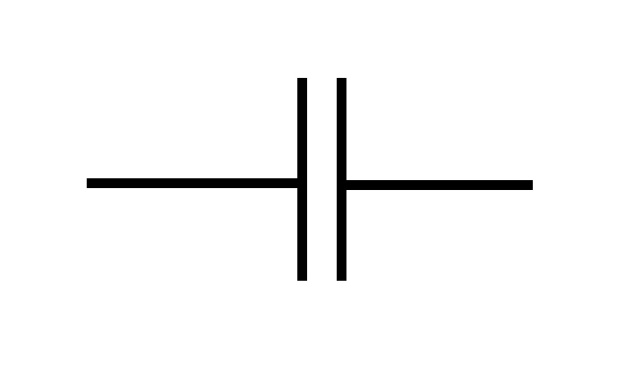
A capacitor consists of two parallel plates separated by a dielectric material. Current cannot flow through the dielectric; instead, charge is stored on the plates. The circuit symbol of a capacitor is effective!
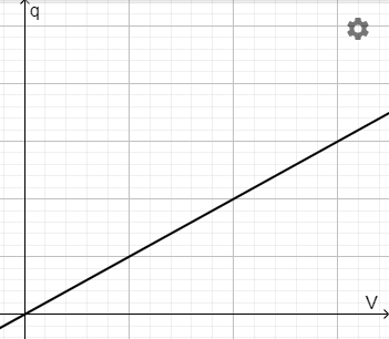
The capacitance of a capacitor is defined as the ratio of the charge stored to the potential difference across the capacitor:
\(C={q\over V}\)
- \(C\) is capacitance (F)
- \(q\) is charge (C)
- \(V\) is potential difference (V)
For a fixed capacitance, \(q=CV\). Capacitance can be determined from the gradient of a charge-potential difference graph.
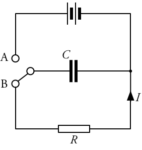
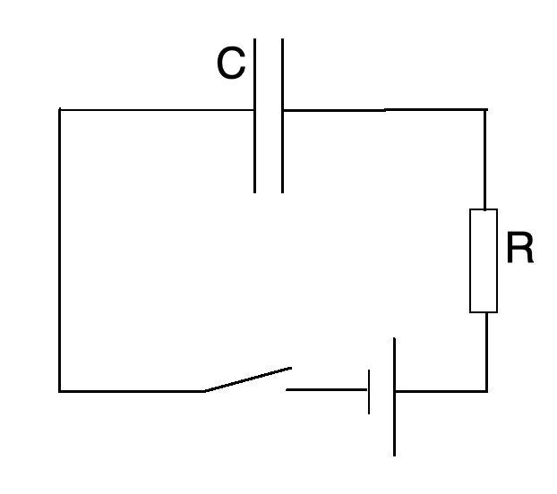
Circuit diagram
Capacitors are charged when connected in series with a power supply (position A in the diagram below). The charge stored is at a maximum when the potential difference on the capacitor rises to match the power supply. At this point, no current flows.
Capacitors discharge through a given resistor when not connected to a power supply (position B). The current is maximum at first. As the charge stored on the capacitor decreases, so does the potential difference across it. The current falls.
Exponential relationships
The repelling nature of the charges stored has the effect that the rate of discharge from a capacitor is proportional to the charge remaining on a capacitor. Mathematically, \(-{\mathrm{d}q\over \mathrm{d}t}\propto q\). Expressions for the variation of charge, current and potential difference with time can be derived:
\(q=q_0e^{-t\over \tau}\)
\(I=I_0e^{-t\over \tau}\)
\(V=V_0e^{-t\over \tau}\)
- \(q\) is the remaining charge stored on the capacitor (C)
- \(q_0\) is the initial charge stored on the capacitor (C)
- \(I\) is the current (A)
- \(I_0\) is the initial current (A)
- \(V\) is the potential difference across the capacitor (C)
- \(V_0\) is the initial potential difference across the capacitor (C)
- \(t\) is the time over which the capacitor has been discharging (s)
- \(\tau\) is the time constant (s)
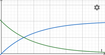
These equations are exponential decay relationships and have the following characteristic shape when plotted against time:
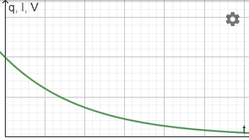
When a capacitor is charged:
- the charge stored and potential difference increase (blue)
- current decreases (green)
Time constant
The time constant for a capacitor circuit is defined as the time taken for the charge, current or potential difference to fall to \(1\over e\) of their original value. This is approximately \(0.37q_0\), \(0.37I_0\) or \(0.37 V_0\).
The time constant can be found from the graph in one of two ways:
- Moving down the vertical axis to find \(0.37q_0\), etc, and then going across to the curve and down to the time.
- Drawing a tangent to the curve at \(t=0\) and extrapolating until it cuts the time axis.
Time constant also has a real-world meaning. It is the product of the capacitance and load resistance (for the circuit diagram shown above):
\(\tau=RC\)
- \(\tau\) is time constant (s)
- \(R\) is load resistance (\(\Omega\))
- \(C\) is capacitance (F)
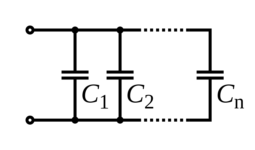
Like other circuit components, capacitors can be connected in series and in parallel.
In parallel, the potential difference on each capacitor is in the same direction; each stores charge in the same orientation. The total capacitance for capacitors in parallel is the sum of the individual capacitances:
\(C_\text{parallel}=C_1+C_2+...+C_n\)
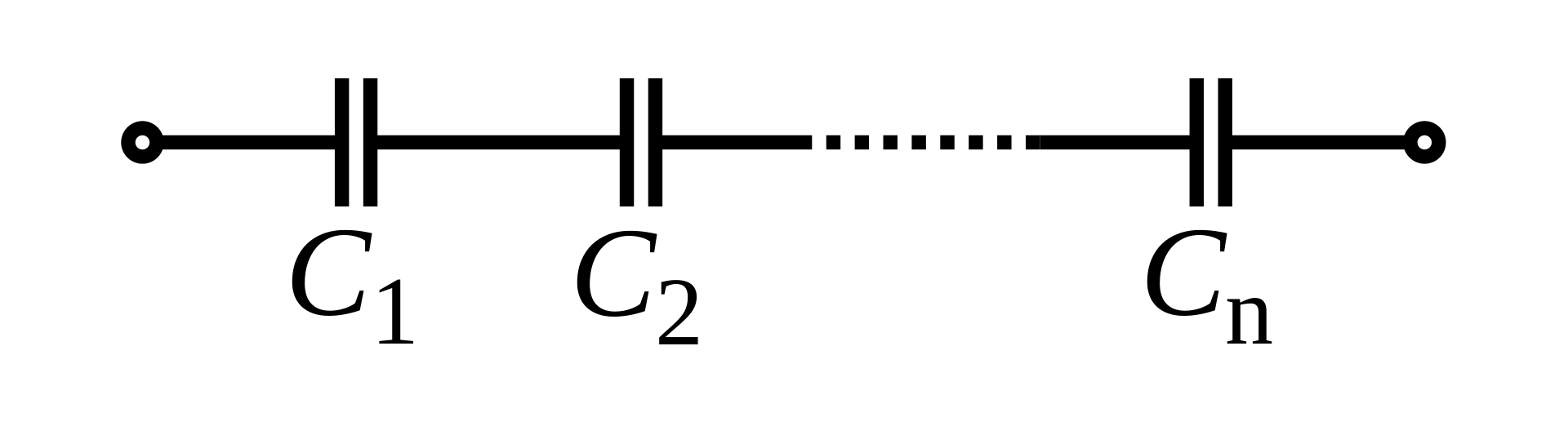
In series, the capacitors counteract one another. The total capacitance is less than any individual capacitor:
\({1\over C_\text{series}}={1\over C_1}+{1\over C_2}+...+{1\over C_n}\)
A capacitor contains a uniform electric field. The value of the capacitance of a capacitor is set according to three variables:
\(C=\varepsilon{A\over d}\)
- \(C\) is capacitance (F)
- \(\varepsilon\) is an electric constant (Fm−1)
- \(A\) is the area of overlap of the two plates (m2)
- \(d\) is the separation between the plates (m)
The electric constant is the product of the permittivity of free space and the relative permittivity of the dielectric:
\(\varepsilon=\varepsilon_0k\)
- \(\varepsilon_0\) is the permittivity of space (8.854 x 10⁻¹² Fm-1)
- \(k\) is the permittivity of the dielectric (~1 for air and >1 for all media)
Capacitors can be used in rectification to overcome the sinusoidal limitation of full wave diode rectification. The presence of a capacitor in parallel with the load smooths the current through the resistor by continuing to release charge even when the EMF across the power supply falls to zero. This has a smoothing effect.
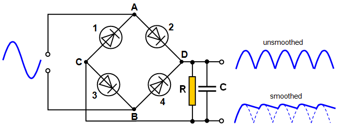
This bridge circuit can appear to be complex at first. However, tracing the flow of current upward from the power supply through A, D, R, C, B and back to the bottom of the power supply shows that diode bias is adhered to throughout.

Use quizzes to practise application of theory.
START QUIZ!
The image shows two metal spheres.
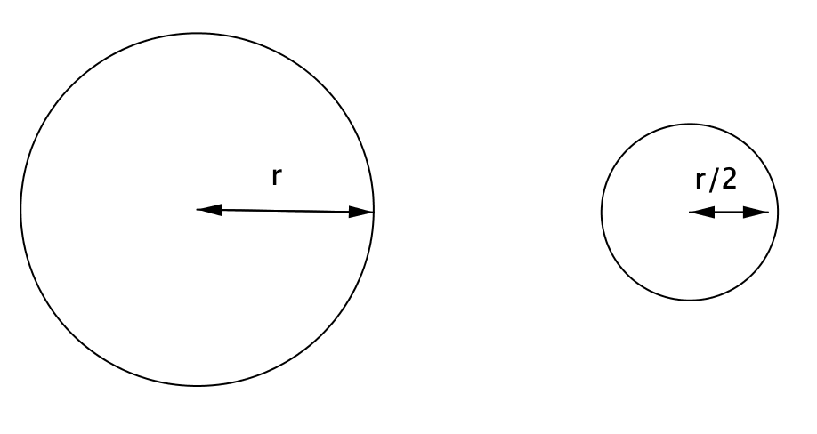
Charge +\(Q\) is added to the large sphere. What charge should be added to the small sphere so that it is at the same potential?
Electrical potential, \(V = {Q\over 4πε_0r}\)
For the same potential, \(Q\propto r\)
The image shows two metal spheres.
The capacitance of the large sphere is 10 pF. What is the capacitance of the small sphere?
\(C = 4πε_0r\Rightarrow C\propto r\)
The image shows two metal spheres.
Adding charge \(+Q\) to the large sphere raises its potential to 10 V. What will the potential difference between the spheres be if \(-Q\) is added to the small sphere?
The small one has half the radius and so half the capacitance. For the same charge, \(V\propto {1\over r}\) and so the potential is -20 V.
The difference in potential \(= 10-(-20) = 30 \text{ V}\)
An adjustable circular parallel plate capacitor has capacitance 16 pF.
What would the capacitance be if both plate separation and plate radius are doubled?
\(C\propto {A\over d}\propto {r^2\over d}\)
The overall effect is x2.
An adjustable circular parallel plate capacitor has capacitance 16 pF.
A dielectric is put between the plates and their separation is reduced to one fifth of the original. If the new capacitance is 0.16 nF, what is the dielectric constant of the material?
Since area is constant, \(C \propto {ε\over d }\)
The capacitance is 10x bigger, so \(ε\over d\) must be 10x bigger. The reduction in separation contributes 5x and so the dielectric constant must be 2x the dielectric constant of air (1 Fm-1).
NB: Don't forget to check unit prefixes p = 10-12 n = 10-9
Charge \(Q\) is transferred to the plates of an adjustable parallel plate capacitor by connecting to a battery of EMF \(V\). If the plate separation is doubled while still connected to the battery, what will the potential difference across and charge stored on the plates be?
Since the capacitor is connected to the same battery, \(V\) is the same.
The capacitance has halved (\(C\propto {1\over d}\)), the charge stored will half (\(q\propto C\)).
Charge \(Q \) is transferred to the plates of an adjustable parallel plate capacitor by connecting to a battery of EMF \(V\). If the battery is disconnected and the plate separation doubled, what will the potential difference across and charge stored on the plates be?
The plates are isolated so \(Q\) is constant so field is constant.
The distance between plates is doubled, so the work done moving between them has been doubled. This implies that potential difference is doubled.
The effect of placing a dielectric between the plates of a capacitor is to reduce the:
The placement of the dielectric implies that the previous material was air, with a permittivity of 1. This can only increase the permittivity and, therefore, the capacitance since \(C\propto \varepsilon\)
\(Q=CV\) so charge would be increased for a given potential difference
\(V={Q\over C}\) so potential difference would be reduced for a given charge
Two capacitors are connected in series.
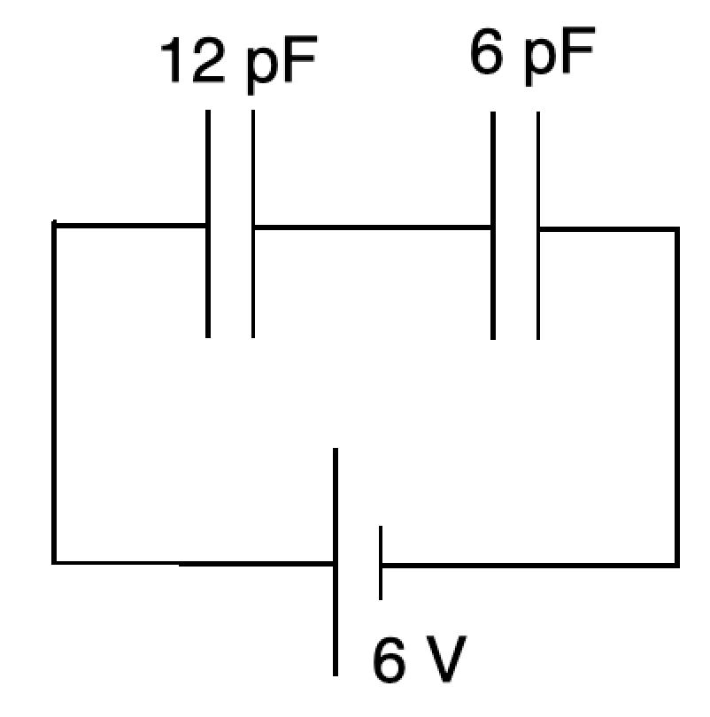
Calculate the total capacitance.
Try this without a calculator!
\({1\over C} = {1\over C_1} + {1\over C_2} = {1\over 12} + {1\over 6} = {1\over12} + {2\over12} = {3\over 12}={1\over 4}\)
\(C_\text{series} = 4\text{ pF}\)
Two capacitors are connected in series.
Calculate the total charge stored.
\({1\over C} = {1\over C_1} + {1\over C_2} = {1\over 12} + {1\over 6} = {1\over12} + {2\over12} = {3\over 12}={1\over 4}\)
\(C_\text{series} = 4\text{ pF}\)
\(Q = CV = 4 \times 6=24\text{ C}\)
Two capacitors are connected in series.
Calculate the charge stored on the 12 pF capacitor.
No charge is stored in the gap between the capacitors since it cannot be added or taken away from the conductor. Therefore the charge is the same as it is for the combination.
\({1\over C} = {1\over C_1} + {1\over C_2} = {1\over 12} + {1\over 6} = {1\over12} + {2\over12} = {3\over 12}={1\over 4}\)
\(C_\text{series} = 4\text{ pF}\)
\(Q = CV = 4 \times 6=24\text{ C}\)
Two capacitors are connected in series.
Calculate the potential difference across the 12 pF capacitor.
To start we will find the charge on the 12 pF capacitor, which is the same as the charge stored for the combination.
\({1\over C} = {1\over C_1} + {1\over C_2} = {1\over 12} + {1\over 6} = {1\over12} + {2\over12} = {3\over 12}={1\over 4}\)
\(C_\text{series} = 4\text{ pF}\)
\(Q = CV = 4 \times 6=24\text{ C}\)
And now the potential difference \(V = {Q\over C} = {24\over 12} = 2\text{ V}\)
Two capacitors are connected in parallel.
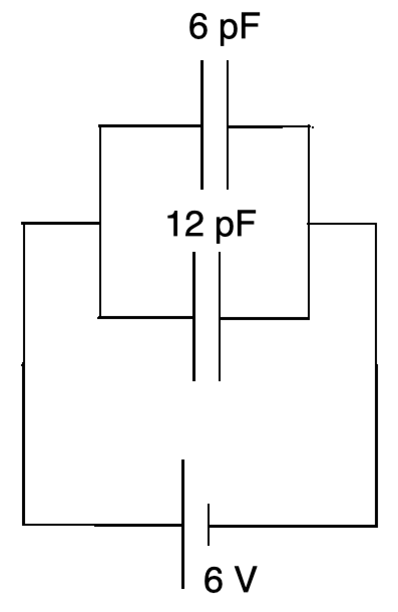
Calculate the total capacitance.
\(C = C_1 + C_2\)
Two capacitors are connected in parallel.
Calculate the charge on the 6 pF capacitor.
The potential difference acts across each of the capacitors.
\(Q = CV=6\text{ pF}\times 6\text{ V}=36\text{ pC}\)
Two capacitors are connected in parallel.
Calculate the ratio \(V_\text{12 pF} \over V_\text{6 pF}\).
The potential difference across each of the capacitors is the same because each is in parallel with the power supply.
START QUIZ!
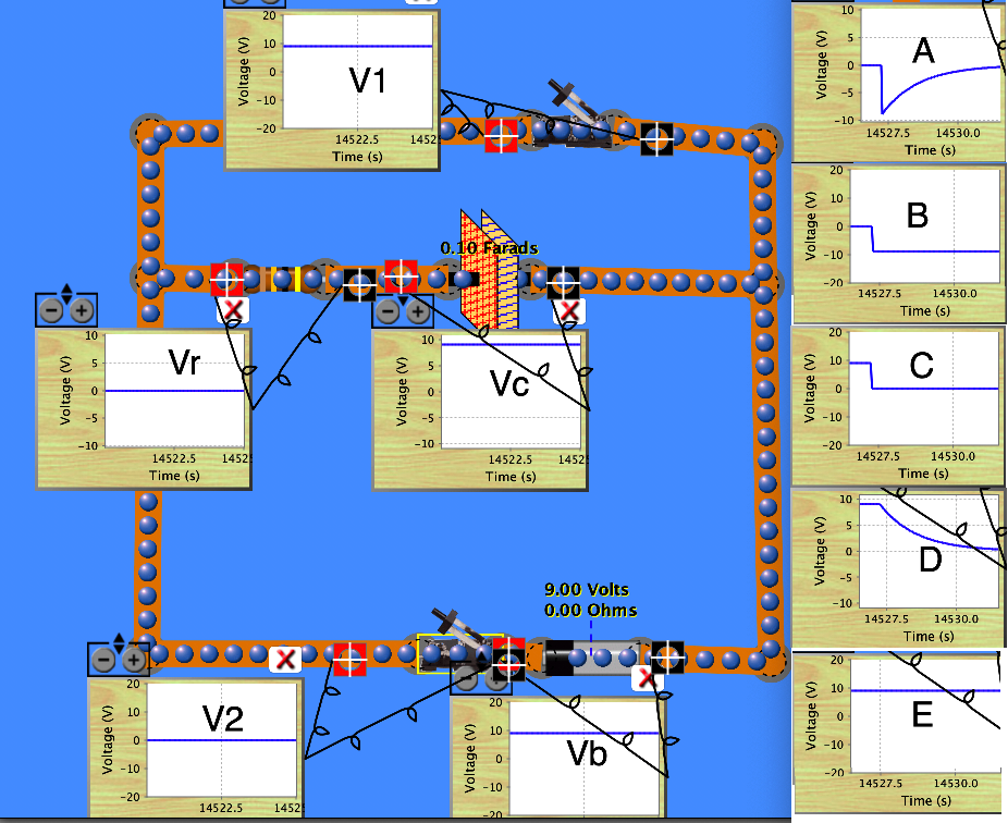
The image is from the PhET circuit simulator. The right hand side shows a list of possible potential difference graphs for each of the voltmeters connected in the circuit.
The capacitor is uncharged. Vb is connected across a cell.
Fill in the letters representing the graphs of the changing potential differences when switch 2 is closed.
V1
Vr
Vc
V2
Vb
Watch and see! Notice the shape of the rising potential difference across the capacitor and the corresponding decrease for the resistor in series.
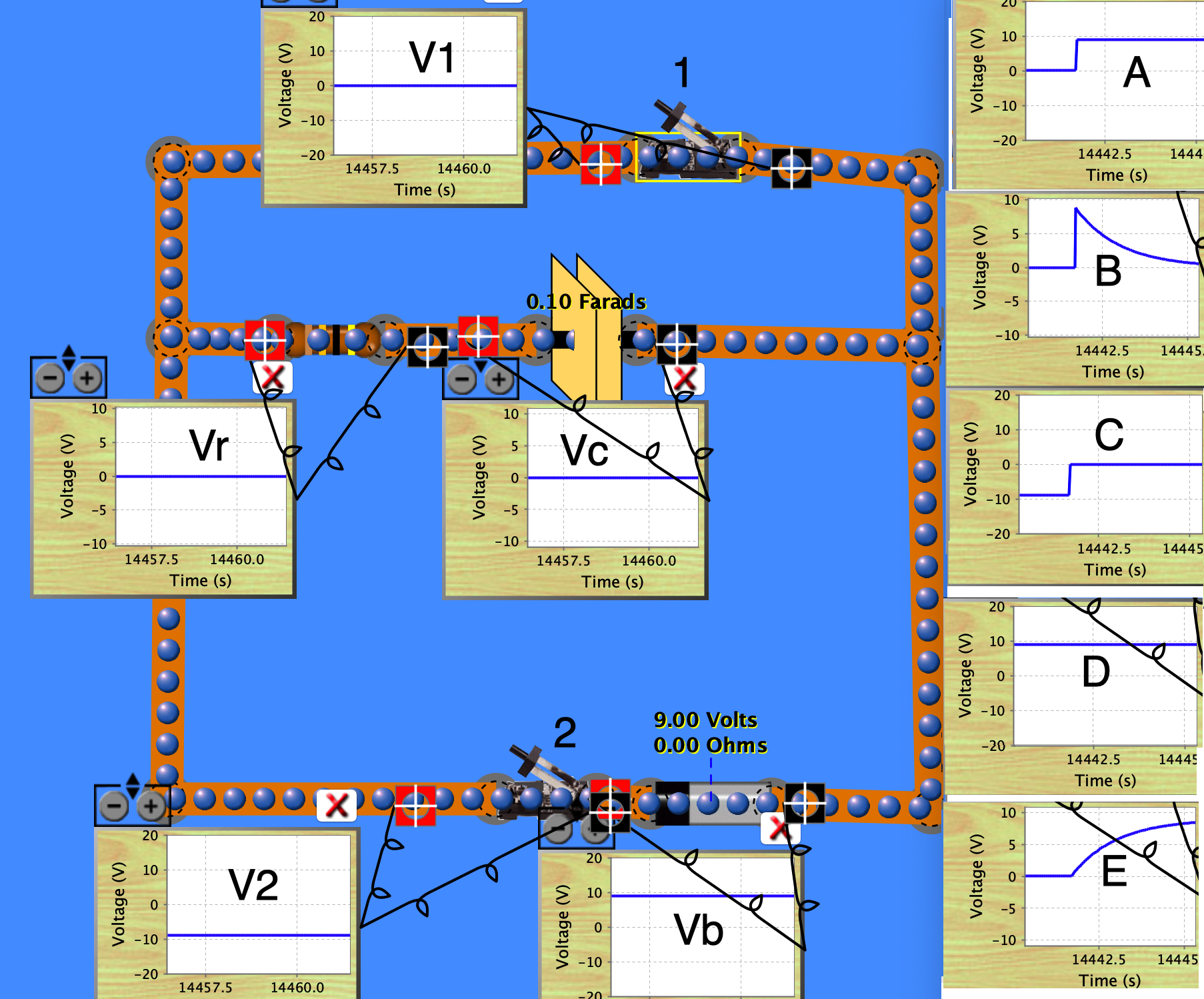
The image is from the PhET circuit simulator. The right hand side shows a list of possible potential difference graphs for each of the voltmeters connected in the circuit.
The capacitor is charged.
Fill in the letters representing the graphs of the changing potential differences when switch 1 (the top switch) is closed.
V1
Vr
Vc
V2
Vb
Watch and see! Notice the shape of the decreasing potential difference across the capacitor and the corresponding increase for the resistor in series.
A capacitor is charged through a resistor. The final potential difference across the plates is \(V\) and the time taken to reach \({2\over3}V\) is \(T\) seconds.
The separation of the plates is doubled. The final potential difference and the time to reach \(2\over3\) of that value is now:
The capacitance is halved since \(C\propto{1\over d}\), so \(CR\) is halved. This means the time constant (approximately the time needed for a charging capacitor's potential difference to rise to \(2\over3\) of its final value) halves.
The final potential difference is unchanged as the power supply is unchanged.
A capacitor is charged through a resistor.
If \(C\) is 10 μF and it takes 20 s to reach 2/3 of its final charge, what is resistance \(R\)?
\(\tau=CR = 20\text{ s}\)
\(R = {20\over10\times10^{-6}} = 2 \times 10^6\text{ Ω}\)
Two capacitors are connected in series.
What is the ratio \(\text{energy stored}_\text{12 pF} \over\text{energy stored}_\text{6 pF}\)?
\(E = {1\over2}{Q^2\over C}\) and \(Q\) is the same for each
\(\Rightarrow E\propto{1\over C}\)
Two capacitors are connected in parallel.
What is the ratio \(\text{energy stored}_\text{12 pF} \over\text{energy stored}_\text{6 pF}\)?
\(E = {1\over 2}CV^2\) and \(V\) is the same for each
\(\Rightarrow E\propto C\)
The graph shows the potential difference across a 2 μF capacitor as it discharges through a resistor, R.
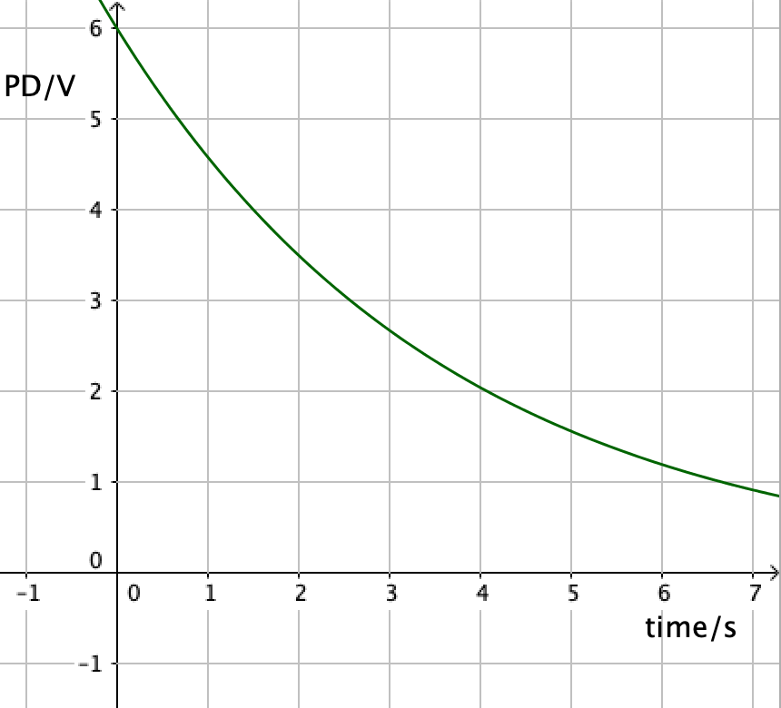
What is the resistance of R?
The time taken to reach \(1\over3\) of initial potential difference, \(\tau =RC = 4\)
\(R={4\over 2\times10^{-6}}=2\times 10^6\text{ }\Omega\)
How much of Capacitors have you understood?
 Twitter
  Facebook
  LinkedIn