| Syllabus sections » |
11.3 – Capacitance
Description
Nature of science:
Relationships: Examples of exponential growth and decay pervade the whole of science. It is a clear example of the way that scientists use mathematics to model reality. This topic can be used to create links between physics topics but also to uses in chemistry, biology, medicine and economics. (3.1)
Understandings:
- Capacitance
- Dielectric materials
- Capacitors in series and parallel
- Resistor-capacitor (RC) series circuits
- Time constant
Applications and skills:
- Describing the effect of different dielectric materials on capacitance
- Solving problems involving parallel-plate capacitors
- Investigating combinations of capacitors in series or parallel circuits
- Determining the energy stored in a charged capacitor
- Describing the nature of the exponential discharge of a capacitor
- Solving problems involving the discharge of a capacitor through a fixed resistor
- Solving problems involving the time constant of an RC circuit for charge, voltage and current
Guidance:
- Only single parallel-plate capacitors providing a uniform electric field, in series with a load, need to be considered (edge effect will be neglected)
- Problems involving the discharge of capacitors through fixed resistors need to be treated both graphically and algebraically
- Problems involving the charging of a capacitor will only be treated graphically
- Derivation of the charge, voltage and current equations as a function of time is not required
Data booklet reference:

International-mindedness:
- Lightning is a phenomenon that has fascinated physicists from Pliny through Newton to Franklin. The charged clouds form one plate of a capacitor with other clouds or Earth forming the second plate. The frequency of lightning strikes varies globally, being particularly prevalent in equatorial regions. The impact of lightning strikes is significant, with many humans and animals being killed annually and huge financial costs to industry from damage to buildings, communication and power transmission systems, etc
Utilization:
- The charge and discharge of capacitors obeys rules that have parallels in other branches of physics including radioactivity (see Physics sub-topic 7.1)
Aims:
- Aim 3: the treatment of exponential growth and decay by graphical and algebraic methods offers both the visual and rigorous approach so often characteristic of science and technology
- Aim 6: experiments could include (but are not limited to): investigating basic RC circuits; using a capacitor in a bridge circuit; examining other types of capacitors; verifying time constant
Directly related questions
-
20N.1.HL.TZ0.36:
A capacitor of capacitance has initial charge . The capacitor is discharged through a resistor of resistance . The potential difference across the capacitor varies with time.
What is true for this capacitor?
A. After time the potential difference across the capacitor is halved.
B. The capacitor discharges more quickly when the resistance is changed to .
C. The rate of change of charge on the capacitor is proportional to .
D. The time for the capacitor to lose half its charge is .
- 17N.1.HL.TZ0.38: A capacitor of capacitance C discharges through a resistor of resistance R. The graph shows...
- 17N.1.HL.TZ0.38: A capacitor of capacitance C discharges through a resistor of resistance R. The graph shows...
- 21M.2.HL.TZ1.5c.i: Describe what happens to the energy stored in the capacitor when the switch is moved to position B.
- 21M.2.HL.TZ1.5c.i: Describe what happens to the energy stored in the capacitor when the switch is moved to position B.
- 21M.2.HL.TZ1.c.i: Describe what happens to the energy stored in the capacitor when the switch is moved to position B.
-
21M.1.HL.TZ1.36:
A capacitor of capacitance X is connected to a power supply of voltage V. At time t = 0, the capacitor is disconnected from the supply and discharged through a resistor of resistance R. What is the variation with time of the charge on the capacitor?
-
21M.1.HL.TZ1.36:
A capacitor of capacitance X is connected to a power supply of voltage V. At time t = 0, the capacitor is disconnected from the supply and discharged through a resistor of resistance R. What is the variation with time of the charge on the capacitor?
- 21M.1.HL.TZ2.33: A parallel-plate capacitor is connected to a cell of constant emf. The capacitor plates are then...
- 21M.1.HL.TZ2.33: A parallel-plate capacitor is connected to a cell of constant emf. The capacitor plates are then...
-
21M.1.HL.TZ2.36:
A capacitor is charged with a constant current . The graph shows the variation of potential difference across the capacitor with time . The gradient of the graph is . What is the capacitance of the capacitor?

A.
B.
C.
D.
-
21M.1.HL.TZ2.36:
A capacitor is charged with a constant current . The graph shows the variation of potential difference across the capacitor with time . The gradient of the graph is . What is the capacitance of the capacitor?
A.
B.
C.
D.
-
18M.2.HL.TZ1.7c:
The capacitor is fully charged and the space between the plates is then filled with a dielectric of permittivity ε = 3.0ε0.
Explain whether the magnitude of the charge on plate A increases, decreases or stays constant.
-
18M.2.HL.TZ1.7c:
The capacitor is fully charged and the space between the plates is then filled with a dielectric of permittivity ε = 3.0ε0.
Explain whether the magnitude of the charge on plate A increases, decreases or stays constant.
-
18M.2.HL.TZ1.c:
The capacitor is fully charged and the space between the plates is then filled with a dielectric of permittivity ε = 3.0ε0.
Explain whether the magnitude of the charge on plate A increases, decreases or stays constant.
- 18M.1.HL.TZ1.36: A parallel plate capacitor is connected to a cell of negligible internal resistance. ...
- 18M.1.HL.TZ1.36: A parallel plate capacitor is connected to a cell of negligible internal resistance. ...
-
18M.2.HL.TZ2.8d:
State one assumption that needs to be made so that the Earth-thundercloud system may be modelled by a parallel plate capacitor.
-
18M.2.HL.TZ2.8d:
State one assumption that needs to be made so that the Earth-thundercloud system may be modelled by a parallel plate capacitor.
-
18M.2.HL.TZ2.d:
State one assumption that needs to be made so that the Earth-thundercloud system may be modelled by a parallel plate capacitor.
-
18M.2.HL.TZ2.8c.i:
Show that about –11 C of charge is delivered to the Earth’s surface.
-
18M.2.HL.TZ2.8c.i:
Show that about –11 C of charge is delivered to the Earth’s surface.
-
18M.2.HL.TZ2.c.i:
Show that about –11 C of charge is delivered to the Earth’s surface.
- 18M.1.HL.TZ2.36: Three capacitors, each one with a capacitance C, are connected such that their...
- 18M.1.HL.TZ2.36: Three capacitors, each one with a capacitance C, are connected such that their...
-
18M.2.HL.TZ2.8a:
Show that the capacitance of this arrangement is C = 6.6 × 10⁻⁷ F.
-
18M.2.HL.TZ2.8a:
Show that the capacitance of this arrangement is C = 6.6 × 10⁻⁷ F.
-
18M.2.HL.TZ2.a:
Show that the capacitance of this arrangement is C = 6.6 × 10⁻⁷ F.
-
18M.2.HL.TZ2.8b.i:
Calculate in V, the potential difference between the thundercloud and the Earth’s surface.
-
18M.2.HL.TZ2.8b.i:
Calculate in V, the potential difference between the thundercloud and the Earth’s surface.
-
18M.2.HL.TZ2.b.i:
Calculate in V, the potential difference between the thundercloud and the Earth’s surface.
-
21N.1.HL.TZ0.36:
Two initially uncharged capacitors X and Y are connected in series to a cell as shown.

What is ?
A.B.
C.
D.
-
21N.1.HL.TZ0.36:
Two initially uncharged capacitors X and Y are connected in series to a cell as shown.
What is ?
A.B.
C.
D.
- 21N.2.HL.TZ0.3c.i: At t = 0, the switch is connected to X. On the axes, draw a sketch graph to show the variation...
- 21N.2.HL.TZ0.3c.i: At t = 0, the switch is connected to X. On the axes, draw a sketch graph to show the variation...
- 21N.2.HL.TZ0.c.i: At t = 0, the switch is connected to X. On the axes, draw a sketch graph to show the variation...
-
21N.2.HL.TZ0.3c.ii:
The switch is then connected to Y and C discharges through the 20 MΩ resistor. The voltage Vc drops to 50 % of its initial value in 5.0 s. Determine the capacitance of C.
-
21N.2.HL.TZ0.3c.ii:
The switch is then connected to Y and C discharges through the 20 MΩ resistor. The voltage Vc drops to 50 % of its initial value in 5.0 s. Determine the capacitance of C.
-
21N.2.HL.TZ0.c.ii:
The switch is then connected to Y and C discharges through the 20 MΩ resistor. The voltage Vc drops to 50 % of its initial value in 5.0 s. Determine the capacitance of C.
- 18N.2.HL.TZ0.7c: An additional identical capacitor is connected in series with the first capacitor and...
- 18N.2.HL.TZ0.7c: An additional identical capacitor is connected in series with the first capacitor and...
- 18N.2.HL.TZ0.c: An additional identical capacitor is connected in series with the first capacitor and...
- 22M.1.HL.TZ1.37: Three identical capacitors are connected together as shown. What is the order of increasing...
- 22M.1.HL.TZ1.37: Three identical capacitors are connected together as shown. What is the order of increasing...
-
22M.2.HL.TZ1.8a:
Show that the charge stored on C1 is about 0.04 mC.
-
22M.2.HL.TZ1.8a:
Show that the charge stored on C1 is about 0.04 mC.
-
22M.2.HL.TZ1.a:
Show that the charge stored on C1 is about 0.04 mC.
-
22M.2.HL.TZ1.8b.i:
Calculate the energy transferred from capacitor C1.
-
22M.2.HL.TZ1.8b.i:
Calculate the energy transferred from capacitor C1.
-
22M.2.HL.TZ1.b.i:
Calculate the energy transferred from capacitor C1.
-
22M.2.HL.TZ1.8b.ii:
Explain why the energy gained by capacitor C2 differs from your answer in (b)(i).
-
22M.2.HL.TZ1.8b.ii:
Explain why the energy gained by capacitor C2 differs from your answer in (b)(i).
-
22M.2.HL.TZ1.b.ii:
Explain why the energy gained by capacitor C2 differs from your answer in (b)(i).
-
19M.2.HL.TZ1.8a.i:
Calculate the total length of aluminium foil that the student will require.
-
19M.2.HL.TZ1.8a.i:
Calculate the total length of aluminium foil that the student will require.
-
19M.2.HL.TZ1.a.i:
Calculate the total length of aluminium foil that the student will require.
-
19M.2.HL.TZ1.8b.i:
The resistor R in the circuit has a resistance of 1.2 kΩ. Calculate the time taken for the charge on the capacitor to fall to 50 % of its fully charged value.
-
19M.2.HL.TZ1.8b.i:
The resistor R in the circuit has a resistance of 1.2 kΩ. Calculate the time taken for the charge on the capacitor to fall to 50 % of its fully charged value.
-
19M.2.HL.TZ1.b.i:
The resistor R in the circuit has a resistance of 1.2 kΩ. Calculate the time taken for the charge on the capacitor to fall to 50 % of its fully charged value.
- 19M.1.HL.TZ1.36: Two capacitors of 3 μF and 6 μF are connected in series and charged using a 9 V battery. What...
- 19M.1.HL.TZ1.36: Two capacitors of 3 μF and 6 μF are connected in series and charged using a 9 V battery. What...
- 19M.1.SL.TZ1.20: Two charges, +Q and −Q, are placed as shown. What is the magnitude of the electric field...
- 19M.1.SL.TZ1.20: Two charges, +Q and −Q, are placed as shown. What is the magnitude of the electric field...
-
19N.2.HL.TZ0.9b(i):
Calculate the final charge on X and the final charge on Y.
-
19N.2.HL.TZ0.9b(i):
Calculate the final charge on X and the final charge on Y.
-
19N.2.HL.TZ0.b(i):
Calculate the final charge on X and the final charge on Y.
-
19N.2.HL.TZ0.9b(ii):
Calculate the final total energy, in J, stored in X and Y.
-
19N.2.HL.TZ0.9b(ii):
Calculate the final total energy, in J, stored in X and Y.
-
19N.2.HL.TZ0.b(ii):
Calculate the final total energy, in J, stored in X and Y.
-
19N.2.HL.TZ0.9a:
Calculate, in J, the energy stored in X with the switch S open.
-
19N.2.HL.TZ0.9a:
Calculate, in J, the energy stored in X with the switch S open.
-
19N.2.HL.TZ0.a:
Calculate, in J, the energy stored in X with the switch S open.
-
22N.1.HL.TZ0.30:
A parallel-plate capacitor is fully charged using a battery.

The capacitor has a capacitance C and a charge Q. The plates X and Y of the capacitor are a distance d apart. Edge effects are negligible.
Three statements about the fully charged capacitor are:
I. The electric field strength between the plates is .
II. The electric field lines are at right angles to the plates.
III. The equipotential surfaces are parallel to the plates.
Which statements are correct?
A. I and II onlyB. I and III only
C. II and III only
D. I, II and III
-
22N.1.HL.TZ0.30:
A parallel-plate capacitor is fully charged using a battery.
The capacitor has a capacitance C and a charge Q. The plates X and Y of the capacitor are a distance d apart. Edge effects are negligible.
Three statements about the fully charged capacitor are:
I. The electric field strength between the plates is .
II. The electric field lines are at right angles to the plates.
III. The equipotential surfaces are parallel to the plates.
Which statements are correct?
A. I and II onlyB. I and III only
C. II and III only
D. I, II and III
-
22N.2.HL.TZ0.9c.i:
Draw, on the axes, a graph to show the variation with time of the current in the resistor.

-
22N.2.HL.TZ0.9c.i:
Draw, on the axes, a graph to show the variation with time of the current in the resistor.
-
22N.2.HL.TZ0.c.i:
Draw, on the axes, a graph to show the variation with time of the current in the resistor.
-
22N.2.HL.TZ0.9a:
Calculate the energy stored in the capacitor.
-
22N.2.HL.TZ0.9a:
Calculate the energy stored in the capacitor.
-
22N.2.HL.TZ0.a:
Calculate the energy stored in the capacitor.
-
22N.2.HL.TZ0.9b.i:
Explain the change, if any, to the potential difference between the plates.
-
22N.2.HL.TZ0.9b.i:
Explain the change, if any, to the potential difference between the plates.
-
22N.2.HL.TZ0.b.i:
Explain the change, if any, to the potential difference between the plates.
-
22N.2.HL.TZ0.9b.ii:
Determine the work required to increase the separation of the plates.
-
22N.2.HL.TZ0.9b.ii:
Determine the work required to increase the separation of the plates.
-
22N.2.HL.TZ0.b.ii:
Determine the work required to increase the separation of the plates.
-
17N.1.HL.TZ0.37:
Six identical capacitors, each of value C, are connected as shown.

What is the total capacitance?
A.
B.
C.
D. 6C
-
17N.1.HL.TZ0.37:
Six identical capacitors, each of value C, are connected as shown.
What is the total capacitance?
A.
B.
C.
D. 6C
-
18M.2.HL.TZ1.7a:
Calculate the distance between the plates.
-
18M.2.HL.TZ1.7a:
Calculate the distance between the plates.
-
18M.2.HL.TZ1.a:
Calculate the distance between the plates.
-
18M.2.HL.TZ1.7b:
The capacitor is connected to a 16 V cell as shown.
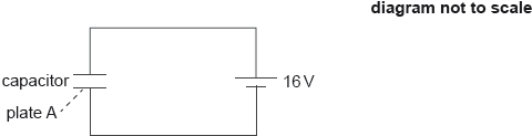
Calculate the magnitude and the sign of the charge on plate A when the capacitor is fully charged.
-
18M.2.HL.TZ1.7b:
The capacitor is connected to a 16 V cell as shown.
Calculate the magnitude and the sign of the charge on plate A when the capacitor is fully charged.
-
18M.2.HL.TZ1.b:
The capacitor is connected to a 16 V cell as shown.
Calculate the magnitude and the sign of the charge on plate A when the capacitor is fully charged.
-
18M.2.HL.TZ2.8b.ii:
Calculate in J, the energy stored in the system.
-
18M.2.HL.TZ2.8b.ii:
Calculate in J, the energy stored in the system.
-
18M.2.HL.TZ2.b.ii:
Calculate in J, the energy stored in the system.
-
18N.1.HL.TZ0.36:
Four identical capacitors of capacitance X are connected as shown in the diagram.

What is the effective capacitance between P and Q?
A.
B. X
C.
D. 4X
-
18N.1.HL.TZ0.36:
Four identical capacitors of capacitance X are connected as shown in the diagram.
What is the effective capacitance between P and Q?
A.
B. X
C.
D. 4X
- 18N.2.HL.TZ0.7a: The battery has an emf of 7.5 V. Determine the charge that flows through the motor when the mass...
- 18N.2.HL.TZ0.7a: The battery has an emf of 7.5 V. Determine the charge that flows through the motor when the mass...
- 18N.2.HL.TZ0.a: The battery has an emf of 7.5 V. Determine the charge that flows through the motor when the mass...
-
18N.2.HL.TZ0.7b:
The motor can transfer one-third of the electrical energy stored in the capacitor into gravitational potential energy of the mass. Determine the maximum height through which a mass of 45 g can be raised.
-
18N.2.HL.TZ0.7b:
The motor can transfer one-third of the electrical energy stored in the capacitor into gravitational potential energy of the mass. Determine the maximum height through which a mass of 45 g can be raised.
-
18N.2.HL.TZ0.b:
The motor can transfer one-third of the electrical energy stored in the capacitor into gravitational potential energy of the mass. Determine the maximum height through which a mass of 45 g can be raised.
-
19M.2.HL.TZ2.4c:
The cell is used to charge a parallel-plate capacitor in a vacuum. The fully charged capacitor is then connected to an ideal voltmeter.

The capacitance of the capacitor is 6.0 μF and the reading of the voltmeter is 12 V.
Calculate the energy stored in the capacitor.
-
19M.2.HL.TZ2.4c:
The cell is used to charge a parallel-plate capacitor in a vacuum. The fully charged capacitor is then connected to an ideal voltmeter.
The capacitance of the capacitor is 6.0 μF and the reading of the voltmeter is 12 V.
Calculate the energy stored in the capacitor.
-
19M.2.HL.TZ2.c:
The cell is used to charge a parallel-plate capacitor in a vacuum. The fully charged capacitor is then connected to an ideal voltmeter.
The capacitance of the capacitor is 6.0 μF and the reading of the voltmeter is 12 V.
Calculate the energy stored in the capacitor.
-
19M.2.HL.TZ2.4di:
Calculate the change in the energy stored in the capacitor.
-
19M.2.HL.TZ2.4di:
Calculate the change in the energy stored in the capacitor.
-
19M.2.HL.TZ2.di:
Calculate the change in the energy stored in the capacitor.
- 19M.2.HL.TZ2.4dii: Suggest, in terms of conservation of energy, the cause for the above change.
- 19M.2.HL.TZ2.4dii: Suggest, in terms of conservation of energy, the cause for the above change.
- 19M.2.HL.TZ2.dii: Suggest, in terms of conservation of energy, the cause for the above change.
- 19M.2.HL.TZ1.8a.ii: The plastic film begins to conduct when the electric field strength in it exceeds 1.5 MN C–1....
- 19M.2.HL.TZ1.8a.ii: The plastic film begins to conduct when the electric field strength in it exceeds 1.5 MN C–1....
- 19M.2.HL.TZ1.a.ii: The plastic film begins to conduct when the electric field strength in it exceeds 1.5 MN C–1....
-
19M.1.HL.TZ2.27:
Three identical capacitors are connected in series. The total capacitance of the arrangement is mF. The three capacitors are then connected in parallel. What is the capacitance of the parallel arrangement?
A. mF
B. 1 mF
C. 3 mF
D. 81 mF
-
19M.1.HL.TZ2.27:
Three identical capacitors are connected in series. The total capacitance of the arrangement is mF. The three capacitors are then connected in parallel. What is the capacitance of the parallel arrangement?
A. mF
B. 1 mF
C. 3 mF
D. 81 mF
-
19M.1.HL.TZ1.37:
The circuit diagram shows a capacitor that is charged by the battery after the switch is connected to terminal X. The cell has emf V and internal resistance r. After the switch is connected to terminal Y the capacitor discharges through the resistor of resistance R.

What is the nature of the current and magnitude of the initial current in the resistor after the switch is connected to terminal Y?

-
19M.1.HL.TZ1.37:
The circuit diagram shows a capacitor that is charged by the battery after the switch is connected to terminal X. The cell has emf V and internal resistance r. After the switch is connected to terminal Y the capacitor discharges through the resistor of resistance R.
What is the nature of the current and magnitude of the initial current in the resistor after the switch is connected to terminal Y?
- 19N.1.HL.TZ0.35: A capacitor of capacitance 1.0 μF stores a charge of 15 μC. The capacitor is discharged through a...
- 19N.1.HL.TZ0.35: A capacitor of capacitance 1.0 μF stores a charge of 15 μC. The capacitor is discharged through a...
-
19N.2.HL.TZ0.9c:
Suggest why the answers to (a) and (b)(ii) are different.
-
19N.2.HL.TZ0.9c:
Suggest why the answers to (a) and (b)(ii) are different.
-
19N.2.HL.TZ0.c:
Suggest why the answers to (a) and (b)(ii) are different.
-
21M.2.HL.TZ1.5b.i:
Show that the maximum energy stored by the capacitor is about 160 J.
-
21M.2.HL.TZ1.5b.i:
Show that the maximum energy stored by the capacitor is about 160 J.
-
21M.2.HL.TZ1.b.i:
Show that the maximum energy stored by the capacitor is about 160 J.
-
21M.2.HL.TZ1.5b.ii:
Calculate the maximum charge Q0 stored in the capacitor.
-
21M.2.HL.TZ1.5b.ii:
Calculate the maximum charge Q0 stored in the capacitor.
-
21M.2.HL.TZ1.b.ii:
Calculate the maximum charge Q0 stored in the capacitor.
- 21M.2.HL.TZ1.5b.iii: Identify, using the label + on the diagram, the polarity of the capacitor.
- 21M.2.HL.TZ1.5b.iii: Identify, using the label + on the diagram, the polarity of the capacitor.
- 21M.2.HL.TZ1.b.iii: Identify, using the label + on the diagram, the polarity of the capacitor.
-
21M.2.HL.TZ1.5c.ii:
Show that the charge remaining in the capacitor after a time equal to one time constant of the circuit will be 0.37 Q0.
-
21M.2.HL.TZ1.5c.ii:
Show that the charge remaining in the capacitor after a time equal to one time constant of the circuit will be 0.37 Q0.
-
21M.2.HL.TZ1.c.ii:
Show that the charge remaining in the capacitor after a time equal to one time constant of the circuit will be 0.37 Q0.
-
21M.2.HL.TZ1.5c.iii:
The graph shows the variation with time of the charge in the capacitor as it is being discharged through the heart.

Determine the electrical resistance of the closed circuit with the switch in position B.
-
21M.2.HL.TZ1.5c.iii:
The graph shows the variation with time of the charge in the capacitor as it is being discharged through the heart.
Determine the electrical resistance of the closed circuit with the switch in position B.
-
21M.2.HL.TZ1.c.iii:
The graph shows the variation with time of the charge in the capacitor as it is being discharged through the heart.
Determine the electrical resistance of the closed circuit with the switch in position B.
- 21M.2.HL.TZ1.5d: In practice, two electrodes connect the heart to the circuit. These electrodes introduce an...
- 21M.2.HL.TZ1.5d: In practice, two electrodes connect the heart to the circuit. These electrodes introduce an...
- 21M.2.HL.TZ1.d: In practice, two electrodes connect the heart to the circuit. These electrodes introduce an...
- 22M.1.HL.TZ2.36: A circuit consists of three identical capacitors of capacitance C and a battery of voltage V. Two...
- 22M.1.HL.TZ2.36: A circuit consists of three identical capacitors of capacitance C and a battery of voltage V. Two...
-
22N.1.HL.TZ0.36:
A student states three facts about the time constant of a resistor-capacitor series circuit.
I. It is the time required for the capacitor to be charged through the resistor to a voltage of 0.632 V from an initial value of zero, where V is the voltage of the source.
II. It is the time required for the capacitor to be discharged through the resistor to a voltage of 0.632 V, where V is the initial voltage of the capacitor.
III. It is the product of the resistance of the resistor and the capacitance of the capacitor.
Which statements are correct?
A. I and II onlyB. I and III only
C. II and III only
D. I, II and III
-
22N.1.HL.TZ0.36:
A student states three facts about the time constant of a resistor-capacitor series circuit.
I. It is the time required for the capacitor to be charged through the resistor to a voltage of 0.632 V from an initial value of zero, where V is the voltage of the source.
II. It is the time required for the capacitor to be discharged through the resistor to a voltage of 0.632 V, where V is the initial voltage of the capacitor.
III. It is the product of the resistance of the resistor and the capacitance of the capacitor.
Which statements are correct?
A. I and II onlyB. I and III only
C. II and III only
D. I, II and III