| Syllabus sections » |
Topic 11: Electromagnetic induction
Description
Overview of essential ideas for this topic.
11.1: The majority of electricity generated throughout the world is generated by machines that were designed to operate using the principles of electromagnetic induction.
11.2: Generation and transmission of alternating current (ac) electricity has transformed the world.
11.3: Capacitors can be used to store electrical energy for later use.
Directly related questions
-
18M.2.HL.TZ1.7a:
Calculate the distance between the plates.
-
17N.1.HL.TZ0.34:
The plane of a coil is positioned at right angles to a magnetic field of flux density B. The coil has N turns, each of area A. The coil is rotated through 180˚ in time t.

What is the magnitude of the induced emf?
A.
B.
C.
D.
-
17N.1.HL.TZ0.34:
The plane of a coil is positioned at right angles to a magnetic field of flux density B. The coil has N turns, each of area A. The coil is rotated through 180˚ in time t.
What is the magnitude of the induced emf?
A.
B.
C.
D.
-
17N.1.HL.TZ0.35:
The ratio for a transformer is 2.5.
The primary coil of the transformer draws a current of 0.25 A from a 200 V alternating current (ac) supply. The current in the secondary coil is 0.5 A. What is the efficiency of the transformer?
A. 20 %
B. 50 %
C. 80 %
D. 100 %
-
17N.1.HL.TZ0.35:
The ratio for a transformer is 2.5.
The primary coil of the transformer draws a current of 0.25 A from a 200 V alternating current (ac) supply. The current in the secondary coil is 0.5 A. What is the efficiency of the transformer?
A. 20 %
B. 50 %
C. 80 %
D. 100 %
-
17N.1.HL.TZ0.36:
An alternating current (ac) generator produces a peak emf E0 and periodic time T. What are the peak emf and periodic time when the frequency of rotation is doubled?

-
17N.1.HL.TZ0.36:
An alternating current (ac) generator produces a peak emf E0 and periodic time T. What are the peak emf and periodic time when the frequency of rotation is doubled?
-
17N.1.HL.TZ0.37:
Six identical capacitors, each of value C, are connected as shown.

What is the total capacitance?
A.
B.
C.
D. 6C
-
17N.1.HL.TZ0.37:
Six identical capacitors, each of value C, are connected as shown.
What is the total capacitance?
A.
B.
C.
D. 6C
- 17N.1.HL.TZ0.38: A capacitor of capacitance C discharges through a resistor of resistance R. The graph shows...
- 17N.1.HL.TZ0.38: A capacitor of capacitance C discharges through a resistor of resistance R. The graph shows...
- 17N.2.HL.TZ0.2c: The cable between the satellites cuts the magnetic field lines of the Earth at right...
- 17N.2.HL.TZ0.2e: The magnetic field strength of the Earth is 31 μT at the orbital radius of the satellites. The...
- 17N.2.HL.TZ0.2e: The magnetic field strength of the Earth is 31 μT at the orbital radius of the satellites. The...
- 17N.2.HL.TZ0.e: The magnetic field strength of the Earth is 31 μT at the orbital radius of the satellites. The...
- 18M.1.HL.TZ1.33: Two identical circular coils are placed one below the other so that their planes are both...
- 18M.1.HL.TZ1.33: Two identical circular coils are placed one below the other so that their planes are both...
-
18M.2.HL.TZ1.7a:
Calculate the distance between the plates.
- 18M.1.HL.TZ1.34: The graph shows the variation with time t of the current I in the primary coil of an ideal...
-
18M.2.HL.TZ1.a:
Calculate the distance between the plates.
-
18M.2.HL.TZ1.7b:
The capacitor is connected to a 16 V cell as shown.
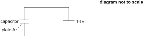
Calculate the magnitude and the sign of the charge on plate A when the capacitor is fully charged.
- 18M.1.HL.TZ1.34: The graph shows the variation with time t of the current I in the primary coil of an ideal...
- 18M.1.HL.TZ1.35: The diagram shows a diode bridge rectification circuit and a load resistor. ...
- 17N.2.HL.TZ0.2c: The cable between the satellites cuts the magnetic field lines of the Earth at right...
- 17N.2.HL.TZ0.c: The cable between the satellites cuts the magnetic field lines of the Earth at right...
-
18M.2.HL.TZ1.7b:
The capacitor is connected to a 16 V cell as shown.
Calculate the magnitude and the sign of the charge on plate A when the capacitor is fully charged.
- 18M.1.HL.TZ1.35: The diagram shows a diode bridge rectification circuit and a load resistor. ...
-
18M.2.HL.TZ1.b:
The capacitor is connected to a 16 V cell as shown.
Calculate the magnitude and the sign of the charge on plate A when the capacitor is fully charged.
-
18M.2.HL.TZ1.7c:
The capacitor is fully charged and the space between the plates is then filled with a dielectric of permittivity ε = 3.0ε0.
Explain whether the magnitude of the charge on plate A increases, decreases or stays constant.
- 18M.1.HL.TZ1.36: A parallel plate capacitor is connected to a cell of negligible internal resistance. ...
- 18M.1.HL.TZ1.36: A parallel plate capacitor is connected to a cell of negligible internal resistance. ...
-
18M.2.HL.TZ1.7c:
The capacitor is fully charged and the space between the plates is then filled with a dielectric of permittivity ε = 3.0ε0.
Explain whether the magnitude of the charge on plate A increases, decreases or stays constant.
- 18M.1.HL.TZ2.33: The current I flowing in loop A in a clockwise direction is increasing so as to induce a...
-
18M.2.HL.TZ1.c:
The capacitor is fully charged and the space between the plates is then filled with a dielectric of permittivity ε = 3.0ε0.
Explain whether the magnitude of the charge on plate A increases, decreases or stays constant.
-
18M.2.HL.TZ1.7d:
In a different circuit, a transformer is connected to an alternating current (ac) supply.

The transformer has 100 turns in the primary coil and 1200 turns in the secondary coil. The peak value of the voltage of the ac supply is 220 V. Determine the root mean square (rms) value of the output voltage.
- 18M.1.HL.TZ2.33: The current I flowing in loop A in a clockwise direction is increasing so as to induce a...
-
18M.2.HL.TZ1.7d:
In a different circuit, a transformer is connected to an alternating current (ac) supply.
The transformer has 100 turns in the primary coil and 1200 turns in the secondary coil. The peak value of the voltage of the ac supply is 220 V. Determine the root mean square (rms) value of the output voltage.
- 18M.1.HL.TZ2.34: A rectangular flat coil moves at constant speed through a uniform magnetic field. The direction...
-
18M.2.HL.TZ2.8a:
Show that the capacitance of this arrangement is C = 6.6 × 10⁻⁷ F.
-
18M.2.HL.TZ1.d:
In a different circuit, a transformer is connected to an alternating current (ac) supply.
The transformer has 100 turns in the primary coil and 1200 turns in the secondary coil. The peak value of the voltage of the ac supply is 220 V. Determine the root mean square (rms) value of the output voltage.
-
18M.2.HL.TZ1.7e:
Describe the use of transformers in electrical power distribution.
-
18M.2.HL.TZ2.8a:
Show that the capacitance of this arrangement is C = 6.6 × 10⁻⁷ F.
-
18M.2.HL.TZ2.a:
Show that the capacitance of this arrangement is C = 6.6 × 10⁻⁷ F.
- 18M.1.HL.TZ2.34: A rectangular flat coil moves at constant speed through a uniform magnetic field. The direction...
-
18M.2.HL.TZ1.7e:
Describe the use of transformers in electrical power distribution.
-
18M.1.HL.TZ2.35:
The graph shows the power dissipated in a resistor of 100 Ω when connected to an alternating current (ac) power supply of root mean square voltage (Vrms) 60 V.

What are the frequency of the ac power supply and the average power dissipated in the resistor?

-
18M.2.HL.TZ2.8b.i:
Calculate in V, the potential difference between the thundercloud and the Earth’s surface.
-
18M.2.HL.TZ1.e:
Describe the use of transformers in electrical power distribution.
-
18M.2.HL.TZ2.8b.i:
Calculate in V, the potential difference between the thundercloud and the Earth’s surface.
-
18M.2.HL.TZ2.b.i:
Calculate in V, the potential difference between the thundercloud and the Earth’s surface.
-
18M.1.HL.TZ2.35:
The graph shows the power dissipated in a resistor of 100 Ω when connected to an alternating current (ac) power supply of root mean square voltage (Vrms) 60 V.
What are the frequency of the ac power supply and the average power dissipated in the resistor?
- 18N.2.HL.TZ0.2d.i: Outline how eddy currents reduce transformer efficiency.
- 18M.1.HL.TZ2.36: Three capacitors, each one with a capacitance C, are connected such that their...
- 18M.1.HL.TZ2.36: Three capacitors, each one with a capacitance C, are connected such that their...
-
18N.1.HL.TZ0.33:
A ring of area S is in a uniform magnetic field X. Initially the magnetic field is perpendicular to the plane of the ring. The ring is rotated by 180° about the axis in time T.

What is the average induced emf in the ring?
A. 0
B.
C.
D. -
18N.1.HL.TZ0.33:
A ring of area S is in a uniform magnetic field X. Initially the magnetic field is perpendicular to the plane of the ring. The ring is rotated by 180° about the axis in time T.
What is the average induced emf in the ring?
A. 0
B.
C.
D. -
18M.2.HL.TZ2.8b.ii:
Calculate in J, the energy stored in the system.
-
18M.2.HL.TZ2.8b.ii:
Calculate in J, the energy stored in the system.
-
18M.2.HL.TZ2.b.ii:
Calculate in J, the energy stored in the system.
-
18M.2.HL.TZ2.8c.i:
Show that about –11 C of charge is delivered to the Earth’s surface.
-
18M.2.HL.TZ2.8c.i:
Show that about –11 C of charge is delivered to the Earth’s surface.
-
18M.2.HL.TZ2.c.i:
Show that about –11 C of charge is delivered to the Earth’s surface.
-
18M.2.HL.TZ2.8d:
State one assumption that needs to be made so that the Earth-thundercloud system may be modelled by a parallel plate capacitor.
-
18M.2.HL.TZ2.8d:
State one assumption that needs to be made so that the Earth-thundercloud system may be modelled by a parallel plate capacitor.
-
18M.2.HL.TZ2.d:
State one assumption that needs to be made so that the Earth-thundercloud system may be modelled by a parallel plate capacitor.
- 18N.2.HL.TZ0.7a: The battery has an emf of 7.5 V. Determine the charge that flows through the motor when the mass...
- 18N.2.HL.TZ0.7a: The battery has an emf of 7.5 V. Determine the charge that flows through the motor when the mass...
- 18N.2.HL.TZ0.a: The battery has an emf of 7.5 V. Determine the charge that flows through the motor when the mass...
- 18N.2.HL.TZ0.2d.i: Outline how eddy currents reduce transformer efficiency.
-
18N.2.HL.TZ0.7b:
The motor can transfer one-third of the electrical energy stored in the capacitor into gravitational potential energy of the mass. Determine the maximum height through which a mass of 45 g can be raised.
-
18N.2.HL.TZ0.7b:
The motor can transfer one-third of the electrical energy stored in the capacitor into gravitational potential energy of the mass. Determine the maximum height through which a mass of 45 g can be raised.
-
18N.2.HL.TZ0.b:
The motor can transfer one-third of the electrical energy stored in the capacitor into gravitational potential energy of the mass. Determine the maximum height through which a mass of 45 g can be raised.
-
18N.1.HL.TZ0.34:
The graph shows the variation of the peak output power P with time of an alternating current (ac) generator.

Which graph shows the variation of the peak output power with time when the frequency of rotation is decreased?

-
18N.1.HL.TZ0.34:
The graph shows the variation of the peak output power P with time of an alternating current (ac) generator.
Which graph shows the variation of the peak output power with time when the frequency of rotation is decreased?
- 18N.2.HL.TZ0.d.i: Outline how eddy currents reduce transformer efficiency.
-
18N.2.HL.TZ0.2d.ii:
Determine the peak current in the primary coil when operating with the maximum number of lamps.
-
18N.1.HL.TZ0.35:
A current of 1.0 × 10⁻³ A flows in the primary coil of a step-up transformer. The number of turns in the primary coil is Np and the number of turns in the secondary coil is Ns. One coil has 1000 times more turns than the other coil.
What is and what is the current in the secondary coil for this transformer?

- 18N.2.HL.TZ0.7c: An additional identical capacitor is connected in series with the first capacitor and...
- 18N.2.HL.TZ0.7c: An additional identical capacitor is connected in series with the first capacitor and...
- 18N.2.HL.TZ0.c: An additional identical capacitor is connected in series with the first capacitor and...
-
18N.2.HL.TZ0.2d.ii:
Determine the peak current in the primary coil when operating with the maximum number of lamps.
-
18N.1.HL.TZ0.35:
A current of 1.0 × 10⁻³ A flows in the primary coil of a step-up transformer. The number of turns in the primary coil is Np and the number of turns in the secondary coil is Ns. One coil has 1000 times more turns than the other coil.
What is and what is the current in the secondary coil for this transformer?
-
18N.1.HL.TZ0.36:
Four identical capacitors of capacitance X are connected as shown in the diagram.

What is the effective capacitance between P and Q?
A.
B. X
C.
D. 4X
-
18N.2.HL.TZ0.d.ii:
Determine the peak current in the primary coil when operating with the maximum number of lamps.
- 19M.2.HL.TZ2.10a: While the magnet is moving towards the ring, state why the magnetic flux in the ring is increasing.
-
18N.1.HL.TZ0.36:
Four identical capacitors of capacitance X are connected as shown in the diagram.
What is the effective capacitance between P and Q?
A.
B. X
C.
D. 4X
- 19M.2.HL.TZ2.10a: While the magnet is moving towards the ring, state why the magnetic flux in the ring is increasing.
-
19M.2.HL.TZ2.4c:
The cell is used to charge a parallel-plate capacitor in a vacuum. The fully charged capacitor is then connected to an ideal voltmeter.

The capacitance of the capacitor is 6.0 μF and the reading of the voltmeter is 12 V.
Calculate the energy stored in the capacitor.
-
19M.2.HL.TZ1.8a.i:
Calculate the total length of aluminium foil that the student will require.
- 19M.2.HL.TZ2.a: While the magnet is moving towards the ring, state why the magnetic flux in the ring is increasing.
- 19M.2.HL.TZ2.10b: While the magnet is moving towards the ring, sketch, using an arrow on Diagram 2, the direction...
-
19M.2.HL.TZ1.8a.i:
Calculate the total length of aluminium foil that the student will require.
-
19M.2.HL.TZ1.a.i:
Calculate the total length of aluminium foil that the student will require.
-
19M.2.HL.TZ2.4c:
The cell is used to charge a parallel-plate capacitor in a vacuum. The fully charged capacitor is then connected to an ideal voltmeter.
The capacitance of the capacitor is 6.0 μF and the reading of the voltmeter is 12 V.
Calculate the energy stored in the capacitor.
-
19M.2.HL.TZ2.c:
The cell is used to charge a parallel-plate capacitor in a vacuum. The fully charged capacitor is then connected to an ideal voltmeter.
The capacitance of the capacitor is 6.0 μF and the reading of the voltmeter is 12 V.
Calculate the energy stored in the capacitor.
- 19M.2.HL.TZ2.10b: While the magnet is moving towards the ring, sketch, using an arrow on Diagram 2, the direction...
-
19M.2.HL.TZ2.4di:
Calculate the change in the energy stored in the capacitor.
- 19M.2.HL.TZ2.b: While the magnet is moving towards the ring, sketch, using an arrow on Diagram 2, the direction...
- 19M.2.HL.TZ1.8a.ii: The plastic film begins to conduct when the electric field strength in it exceeds 1.5 MN C–1....
- 19M.2.HL.TZ2.10c: While the magnet is moving towards the ring, deduce the direction of the magnetic force on the...
- 19M.2.HL.TZ1.8a.ii: The plastic film begins to conduct when the electric field strength in it exceeds 1.5 MN C–1....
- 19M.2.HL.TZ1.a.ii: The plastic film begins to conduct when the electric field strength in it exceeds 1.5 MN C–1....
-
19M.2.HL.TZ2.4di:
Calculate the change in the energy stored in the capacitor.
-
19M.2.HL.TZ2.di:
Calculate the change in the energy stored in the capacitor.
- 19M.2.HL.TZ2.10c: While the magnet is moving towards the ring, deduce the direction of the magnetic force on the...
-
19M.2.HL.TZ1.8b.i:
The resistor R in the circuit has a resistance of 1.2 kΩ. Calculate the time taken for the charge on the capacitor to fall to 50 % of its fully charged value.
- 19M.2.HL.TZ2.c: While the magnet is moving towards the ring, deduce the direction of the magnetic force on the...
- 19M.1.SL.TZ1.20: Two charges, +Q and −Q, are placed as shown. What is the magnitude of the electric field...
-
19M.2.HL.TZ1.8b.i:
The resistor R in the circuit has a resistance of 1.2 kΩ. Calculate the time taken for the charge on the capacitor to fall to 50 % of its fully charged value.
-
19M.2.HL.TZ1.b.i:
The resistor R in the circuit has a resistance of 1.2 kΩ. Calculate the time taken for the charge on the capacitor to fall to 50 % of its fully charged value.
- 19M.2.HL.TZ2.4dii: Suggest, in terms of conservation of energy, the cause for the above change.
- 19M.2.HL.TZ2.4dii: Suggest, in terms of conservation of energy, the cause for the above change.
- 19M.2.HL.TZ2.dii: Suggest, in terms of conservation of energy, the cause for the above change.
- 19M.1.SL.TZ1.20: Two charges, +Q and −Q, are placed as shown. What is the magnitude of the electric field...
-
19M.1.HL.TZ1.35:
The graph below shows the variation with time of the magnetic flux through a coil.

Which of the following gives three times for which the magnitude of the induced emf is a maximum?
A. 0, ,
B. 0, , T
C. 0, , T
D. , ,
- 19M.2.HL.TZ1.8b.ii: The ammeter is replaced by a coil. Explain why there will be an induced emf in the coil while the...
-
19M.1.HL.TZ1.35:
The graph below shows the variation with time of the magnetic flux through a coil.
Which of the following gives three times for which the magnitude of the induced emf is a maximum?
A. 0, ,
B. 0, , T
C. 0, , T
D. , ,
- 19M.2.HL.TZ1.8b.ii: The ammeter is replaced by a coil. Explain why there will be an induced emf in the coil while the...
- 19M.2.HL.TZ1.b.ii: The ammeter is replaced by a coil. Explain why there will be an induced emf in the coil while the...
-
19M.2.HL.TZ1.8b.iii:
Suggest one change to the discharge circuit, apart from changes to the coil, that will increase the maximum induced emf in the coil.
- 19M.1.HL.TZ2.26: The input to a diode bridge rectification circuit is sinusoidal with a time period of 20...
- 19M.1.HL.TZ2.26: The input to a diode bridge rectification circuit is sinusoidal with a time period of 20...
- 19M.1.HL.TZ1.36: Two capacitors of 3 μF and 6 μF are connected in series and charged using a 9 V battery. What...
-
19M.1.HL.TZ2.27:
Three identical capacitors are connected in series. The total capacitance of the arrangement is mF. The three capacitors are then connected in parallel. What is the capacitance of the parallel arrangement?
A. mF
B. 1 mF
C. 3 mF
D. 81 mF
-
19M.1.HL.TZ2.28:
A transformer with 600 turns in the primary coil is used to change an alternating root mean square (rms) potential difference of 240 Vrms to 12 Vrms.
When connected to the secondary coil, a lamp labelled “120 W, 12 V” lights normally. The current in the primary coil is 0.60 A when the lamp is lit.
What are the number of secondary turns and the efficiency of the transformer?

-
19M.2.HL.TZ1.8b.iii:
Suggest one change to the discharge circuit, apart from changes to the coil, that will increase the maximum induced emf in the coil.
-
19M.2.HL.TZ1.b.iii:
Suggest one change to the discharge circuit, apart from changes to the coil, that will increase the maximum induced emf in the coil.
-
19M.1.HL.TZ1.37:
The circuit diagram shows a capacitor that is charged by the battery after the switch is connected to terminal X. The cell has emf V and internal resistance r. After the switch is connected to terminal Y the capacitor discharges through the resistor of resistance R.

What is the nature of the current and magnitude of the initial current in the resistor after the switch is connected to terminal Y?

-
19M.1.HL.TZ1.37:
The circuit diagram shows a capacitor that is charged by the battery after the switch is connected to terminal X. The cell has emf V and internal resistance r. After the switch is connected to terminal Y the capacitor discharges through the resistor of resistance R.
What is the nature of the current and magnitude of the initial current in the resistor after the switch is connected to terminal Y?
-
19M.1.HL.TZ2.28:
A transformer with 600 turns in the primary coil is used to change an alternating root mean square (rms) potential difference of 240 Vrms to 12 Vrms.
When connected to the secondary coil, a lamp labelled “120 W, 12 V” lights normally. The current in the primary coil is 0.60 A when the lamp is lit.
What are the number of secondary turns and the efficiency of the transformer?
- 19M.1.HL.TZ2.29: A circular coil of wire moves through a region of uniform magnetic field directed out of the...
-
19N.2.HL.TZ0.9a:
Calculate, in J, the energy stored in X with the switch S open.
- 19M.1.HL.TZ2.29: A circular coil of wire moves through a region of uniform magnetic field directed out of the...
- 19N.1.HL.TZ0.33: X and Y are two plane coils parallel to each other that have a common axis. There is a constant...
-
19N.2.HL.TZ0.9a:
Calculate, in J, the energy stored in X with the switch S open.
- 19N.1.HL.TZ0.33: X and Y are two plane coils parallel to each other that have a common axis. There is a constant...
-
19N.2.HL.TZ0.a:
Calculate, in J, the energy stored in X with the switch S open.
-
19N.2.HL.TZ0.9b(i):
Calculate the final charge on X and the final charge on Y.
- 19N.1.HL.TZ0.34: A coil is rotated in a uniform magnetic field. An alternating emf is induced in the coil. What is...
- 19N.1.HL.TZ0.34: A coil is rotated in a uniform magnetic field. An alternating emf is induced in the coil. What is...
-
19N.2.HL.TZ0.9b(i):
Calculate the final charge on X and the final charge on Y.
-
19N.2.HL.TZ0.b(i):
Calculate the final charge on X and the final charge on Y.
-
19N.2.HL.TZ0.9b(ii):
Calculate the final total energy, in J, stored in X and Y.
- 19N.1.HL.TZ0.35: A capacitor of capacitance 1.0 μF stores a charge of 15 μC. The capacitor is discharged through a...
- 20N.1.HL.TZ0.33: Why are high voltages and low currents used when electricity is transmitted over long...
-
19N.2.HL.TZ0.9b(ii):
Calculate the final total energy, in J, stored in X and Y.
- 20N.1.HL.TZ0.33: Why are high voltages and low currents used when electricity is transmitted over long...
-
19N.2.HL.TZ0.b(ii):
Calculate the final total energy, in J, stored in X and Y.
-
19N.2.HL.TZ0.9c:
Suggest why the answers to (a) and (b)(ii) are different.
-
20N.1.HL.TZ0.34:
Power is dissipated in a resistor of resistance when there is a direct current in the resistor.
What is the average power dissipation in a resistance when the alternating root-mean-square (rms) current in the resistor is ?
A.
B.
C.
D.
- 19N.1.HL.TZ0.35: A capacitor of capacitance 1.0 μF stores a charge of 15 μC. The capacitor is discharged through a...
-
19N.2.HL.TZ0.9c:
Suggest why the answers to (a) and (b)(ii) are different.
- 19N.1.HL.TZ0.36: A diode bridge rectification circuit is constructed as shown. An alternating potential difference...
-
20N.1.HL.TZ0.34:
Power is dissipated in a resistor of resistance when there is a direct current in the resistor.
What is the average power dissipation in a resistance when the alternating root-mean-square (rms) current in the resistor is ?
A.
B.
C.
D.
-
19N.2.HL.TZ0.c:
Suggest why the answers to (a) and (b)(ii) are different.
-
20N.2.HL.TZ0.9a:
Explain, by reference to Faraday’s law of induction, how an electromotive force (emf) is induced in the coil.
-
20N.1.HL.TZ0.35:
A rectangular coil rotates at a constant angular velocity. At the instant shown, the plane of the coil is at right angles to the line . A uniform magnetic field acts in the direction .

What rotation of the coil about a specified axis will produce the graph of electromotive force (emf) against time ?
A. Through about
B. Through about
C. Through about
D. Through about
-
20N.1.HL.TZ0.35:
A rectangular coil rotates at a constant angular velocity. At the instant shown, the plane of the coil is at right angles to the line . A uniform magnetic field acts in the direction .
What rotation of the coil about a specified axis will produce the graph of electromotive force (emf) against time ?
A. Through about
B. Through about
C. Through about
D. Through about
-
20N.1.HL.TZ0.36:
A capacitor of capacitance has initial charge . The capacitor is discharged through a resistor of resistance . The potential difference across the capacitor varies with time.
What is true for this capacitor?
A. After time the potential difference across the capacitor is halved.
B. The capacitor discharges more quickly when the resistance is changed to .
C. The rate of change of charge on the capacitor is proportional to .
D. The time for the capacitor to lose half its charge is .
- 19N.1.HL.TZ0.36: A diode bridge rectification circuit is constructed as shown. An alternating potential difference...
-
20N.2.HL.TZ0.9a:
Explain, by reference to Faraday’s law of induction, how an electromotive force (emf) is induced in the coil.
-
20N.2.HL.TZ0.a:
Explain, by reference to Faraday’s law of induction, how an electromotive force (emf) is induced in the coil.
-
20N.2.HL.TZ0.9b(i):
The average power output of the generator is . Calculate the root mean square (rms) value of the generator output current.
-
20N.2.HL.TZ0.9b(i):
The average power output of the generator is . Calculate the root mean square (rms) value of the generator output current.
-
20N.2.HL.TZ0.b(i):
The average power output of the generator is . Calculate the root mean square (rms) value of the generator output current.
-
20N.2.HL.TZ0.9b(ii):
The voltage output from the generator is stepped up before transmission to the consumer. Estimate the factor by which voltage has to be stepped up in order to reduce power loss in the transmission line by a factor of .
-
20N.2.HL.TZ0.9b(ii):
The voltage output from the generator is stepped up before transmission to the consumer. Estimate the factor by which voltage has to be stepped up in order to reduce power loss in the transmission line by a factor of .
-
20N.2.HL.TZ0.b(ii):
The voltage output from the generator is stepped up before transmission to the consumer. Estimate the factor by which voltage has to be stepped up in order to reduce power loss in the transmission line by a factor of .
-
20N.2.HL.TZ0.9b(iii):
The frequency of the generator is doubled with no other changes being made. Draw, on the axes, the variation with time of the voltage output of the generator.
-
20N.2.HL.TZ0.9b(iii):
The frequency of the generator is doubled with no other changes being made. Draw, on the axes, the variation with time of the voltage output of the generator.
-
20N.2.HL.TZ0.b(iii):
The frequency of the generator is doubled with no other changes being made. Draw, on the axes, the variation with time of the voltage output of the generator.
- 21M.2.HL.TZ1.5a: Explain the role of the diode in the circuit when the switch is at position A.
- 21M.2.HL.TZ1.5a: Explain the role of the diode in the circuit when the switch is at position A.
- 21M.1.HL.TZ1.33: A conducting ring encloses an area of 2.0 cm2 and is perpendicular to a magnetic field...
-
21M.2.HL.TZ2.7a.i:
The primary coil has 3300 turns. Calculate the number of turns on the secondary coil.
- 21M.2.HL.TZ1.a: Explain the role of the diode in the circuit when the switch is at position A.
-
21M.2.HL.TZ1.5b.i:
Show that the maximum energy stored by the capacitor is about 160 J.
- 21M.1.HL.TZ1.33: A conducting ring encloses an area of 2.0 cm2 and is perpendicular to a magnetic field...
-
21M.2.HL.TZ1.5b.i:
Show that the maximum energy stored by the capacitor is about 160 J.
- 21M.1.HL.TZ1.34: The conservation of which quantity explains Lenz’s law? A. Charge B. Energy C. Magnetic...
-
21M.2.HL.TZ2.7a.i:
The primary coil has 3300 turns. Calculate the number of turns on the secondary coil.
-
21M.2.HL.TZ2.a.i:
The primary coil has 3300 turns. Calculate the number of turns on the secondary coil.
-
21M.2.HL.TZ1.b.i:
Show that the maximum energy stored by the capacitor is about 160 J.
-
21M.2.HL.TZ1.5b.ii:
Calculate the maximum charge Q0 stored in the capacitor.
-
21M.2.HL.TZ2.7a.iii:
Calculate the current in the primary of the transformer assuming that it is ideal.
- 21M.1.HL.TZ1.34: The conservation of which quantity explains Lenz’s law? A. Charge B. Energy C. Magnetic...
-
21M.1.HL.TZ1.35:
A resistor designed for use in a direct current (dc) circuit is labelled “50 W, 2 Ω”. The resistor is connected in series with an alternating current (ac) power supply of peak potential difference 10 V. What is the average power dissipated by the resistor in the ac circuit?
A. 25 W
B. 35 W
C. 50 W
D. 100 W
-
21M.2.HL.TZ1.5b.ii:
Calculate the maximum charge Q0 stored in the capacitor.
-
21M.2.HL.TZ1.b.ii:
Calculate the maximum charge Q0 stored in the capacitor.
- 21M.2.HL.TZ1.5b.iii: Identify, using the label + on the diagram, the polarity of the capacitor.
-
21M.1.HL.TZ1.35:
A resistor designed for use in a direct current (dc) circuit is labelled “50 W, 2 Ω”. The resistor is connected in series with an alternating current (ac) power supply of peak potential difference 10 V. What is the average power dissipated by the resistor in the ac circuit?
A. 25 W
B. 35 W
C. 50 W
D. 100 W
-
21M.2.HL.TZ2.7a.iii:
Calculate the current in the primary of the transformer assuming that it is ideal.
-
21M.2.HL.TZ2.a.iii:
Calculate the current in the primary of the transformer assuming that it is ideal.
- 21M.2.HL.TZ1.5b.iii: Identify, using the label + on the diagram, the polarity of the capacitor.
-
21M.2.HL.TZ2.7a.iv:
Flux leakage is one reason why a transformer may not be ideal. Explain the effect of flux leakage on the transformer.
-
21M.1.HL.TZ1.36:
A capacitor of capacitance X is connected to a power supply of voltage V. At time t = 0, the capacitor is disconnected from the supply and discharged through a resistor of resistance R. What is the variation with time of the charge on the capacitor?
- 21M.2.HL.TZ1.b.iii: Identify, using the label + on the diagram, the polarity of the capacitor.
- 21M.2.HL.TZ1.5c.i: Describe what happens to the energy stored in the capacitor when the switch is moved to position B.
-
21M.1.HL.TZ1.36:
A capacitor of capacitance X is connected to a power supply of voltage V. At time t = 0, the capacitor is disconnected from the supply and discharged through a resistor of resistance R. What is the variation with time of the charge on the capacitor?
-
21M.2.HL.TZ2.7a.iv:
Flux leakage is one reason why a transformer may not be ideal. Explain the effect of flux leakage on the transformer.
-
21M.2.HL.TZ2.a.iv:
Flux leakage is one reason why a transformer may not be ideal. Explain the effect of flux leakage on the transformer.
- 21M.2.HL.TZ1.5c.i: Describe what happens to the energy stored in the capacitor when the switch is moved to position B.
- 21M.2.HL.TZ2.7b: A pendulum with a metal bob comes to rest after 200 swings. The same pendulum, released from the...
- 21M.1.HL.TZ2.33: A parallel-plate capacitor is connected to a cell of constant emf. The capacitor plates are then...
- 21M.2.HL.TZ1.c.i: Describe what happens to the energy stored in the capacitor when the switch is moved to position B.
-
21M.2.HL.TZ1.5c.ii:
Show that the charge remaining in the capacitor after a time equal to one time constant of the circuit will be 0.37 Q0.
- 21M.1.HL.TZ2.33: A parallel-plate capacitor is connected to a cell of constant emf. The capacitor plates are then...
-
21M.1.HL.TZ2.34:
The graph shows the variation of an alternating current with time in a resistor.

What is the average power dissipated in the resistor?
A.
B.
C.
D.
- 21M.2.HL.TZ2.7b: A pendulum with a metal bob comes to rest after 200 swings. The same pendulum, released from the...
- 21M.2.HL.TZ2.b: A pendulum with a metal bob comes to rest after 200 swings. The same pendulum, released from the...
-
21M.2.HL.TZ1.5c.ii:
Show that the charge remaining in the capacitor after a time equal to one time constant of the circuit will be 0.37 Q0.
-
21M.2.HL.TZ1.c.ii:
Show that the charge remaining in the capacitor after a time equal to one time constant of the circuit will be 0.37 Q0.
-
21M.2.HL.TZ1.5c.iii:
The graph shows the variation with time of the charge in the capacitor as it is being discharged through the heart.

Determine the electrical resistance of the closed circuit with the switch in position B.
-
21M.1.HL.TZ2.34:
The graph shows the variation of an alternating current with time in a resistor.
What is the average power dissipated in the resistor?
A.
B.
C.
D.
-
21M.1.HL.TZ2.35:
A magnet connected to a spring oscillates above a solenoid with a 240 turn coil as shown.

The graph below shows the variation with time of the emf across the solenoid with the period, , of the system shown.

The spring is replaced with one that allows the magnet to oscillate with a higher frequency. Which graph shows the new variation with time of the current in the resistor for this new set-up?

-
21M.2.HL.TZ1.5c.iii:
The graph shows the variation with time of the charge in the capacitor as it is being discharged through the heart.
Determine the electrical resistance of the closed circuit with the switch in position B.
-
21M.2.HL.TZ1.c.iii:
The graph shows the variation with time of the charge in the capacitor as it is being discharged through the heart.
Determine the electrical resistance of the closed circuit with the switch in position B.
- 21M.2.HL.TZ1.5d: In practice, two electrodes connect the heart to the circuit. These electrodes introduce an...
-
21M.1.HL.TZ2.35:
A magnet connected to a spring oscillates above a solenoid with a 240 turn coil as shown.
The graph below shows the variation with time of the emf across the solenoid with the period, , of the system shown.
The spring is replaced with one that allows the magnet to oscillate with a higher frequency. Which graph shows the new variation with time of the current in the resistor for this new set-up?
-
21M.1.HL.TZ2.36:
A capacitor is charged with a constant current . The graph shows the variation of potential difference across the capacitor with time . The gradient of the graph is . What is the capacitance of the capacitor?

A.
B.
C.
D.
- 21M.2.HL.TZ1.5d: In practice, two electrodes connect the heart to the circuit. These electrodes introduce an...
- 21M.2.HL.TZ1.d: In practice, two electrodes connect the heart to the circuit. These electrodes introduce an...
-
21N.2.HL.TZ0.5a:
Show that the speed of the loop is 20 cm s−1.
-
21M.1.HL.TZ2.36:
A capacitor is charged with a constant current . The graph shows the variation of potential difference across the capacitor with time . The gradient of the graph is . What is the capacitance of the capacitor?
A.
B.
C.
D.
-
21N.2.HL.TZ0.5a:
Show that the speed of the loop is 20 cm s−1.
- 21N.2.HL.TZ0.3c.i: At t = 0, the switch is connected to X. On the axes, draw a sketch graph to show the variation...
- 21N.2.HL.TZ0.3c.i: At t = 0, the switch is connected to X. On the axes, draw a sketch graph to show the variation...
- 21N.2.HL.TZ0.c.i: At t = 0, the switch is connected to X. On the axes, draw a sketch graph to show the variation...
- 21N.1.HL.TZ0.33: A small magnet is released from rest to drop through a stationary horizontal conducting...
- 21N.1.HL.TZ0.33: A small magnet is released from rest to drop through a stationary horizontal conducting...
- 21N.1.HL.TZ0.34: An alternating supply is connected to a diode bridge rectification circuit. The conventional...
- 21N.1.HL.TZ0.34: An alternating supply is connected to a diode bridge rectification circuit. The conventional...
-
21N.2.HL.TZ0.a:
Show that the speed of the loop is 20 cm s−1.
-
21N.2.HL.TZ0.5b.i:
Sketch, on the axes, a graph to show the variation with time of the magnetic flux linkage in the loop.

-
21N.1.HL.TZ0.35:
The root mean square (rms) current in the primary coil of an ideal transformer is 2.0 A. The rms voltage in the secondary coil is 50 V. The average power transferred from the secondary coil is 20 W.
What is and what is the average power transferred from the primary coil?

-
21N.1.HL.TZ0.35:
The root mean square (rms) current in the primary coil of an ideal transformer is 2.0 A. The rms voltage in the secondary coil is 50 V. The average power transferred from the secondary coil is 20 W.
What is and what is the average power transferred from the primary coil?
-
21N.2.HL.TZ0.3c.ii:
The switch is then connected to Y and C discharges through the 20 MΩ resistor. The voltage Vc drops to 50 % of its initial value in 5.0 s. Determine the capacitance of C.
-
21N.2.HL.TZ0.5b.i:
Sketch, on the axes, a graph to show the variation with time of the magnetic flux linkage in the loop.
-
21N.2.HL.TZ0.3c.ii:
The switch is then connected to Y and C discharges through the 20 MΩ resistor. The voltage Vc drops to 50 % of its initial value in 5.0 s. Determine the capacitance of C.
-
21N.2.HL.TZ0.c.ii:
The switch is then connected to Y and C discharges through the 20 MΩ resistor. The voltage Vc drops to 50 % of its initial value in 5.0 s. Determine the capacitance of C.
-
21N.1.HL.TZ0.36:
Two initially uncharged capacitors X and Y are connected in series to a cell as shown.

What is ?
A.B.
C.
D.
-
21N.2.HL.TZ0.b.i:
Sketch, on the axes, a graph to show the variation with time of the magnetic flux linkage in the loop.
-
21N.2.HL.TZ0.5b.ii:
Sketch, on the axes, a graph to show the variation with time of the magnitude of the emf induced in the loop.

-
21N.1.HL.TZ0.36:
Two initially uncharged capacitors X and Y are connected in series to a cell as shown.
What is ?
A.B.
C.
D.
-
21N.2.HL.TZ0.5b.ii:
Sketch, on the axes, a graph to show the variation with time of the magnitude of the emf induced in the loop.
-
21N.2.HL.TZ0.b.ii:
Sketch, on the axes, a graph to show the variation with time of the magnitude of the emf induced in the loop.
-
21N.2.HL.TZ0.5c.i:
There are 85 turns of wire in the loop. Calculate the maximum induced emf in the loop.
-
21N.2.HL.TZ0.5c.i:
There are 85 turns of wire in the loop. Calculate the maximum induced emf in the loop.
-
21N.2.HL.TZ0.c.i:
There are 85 turns of wire in the loop. Calculate the maximum induced emf in the loop.
- 22M.2.HL.TZ2.8a.i: Write down the maximum magnitude of the rate of change of flux linked with the coil.
- 22M.1.HL.TZ2.34: Which two features are necessary for the operation of a transformer?
- 22M.1.HL.TZ2.34: Which two features are necessary for the operation of a transformer?
- 22M.1.HL.TZ2.35: A conducting bar with vertices PQRS is moving vertically downwards with constant velocity v...
- 22M.1.HL.TZ2.36: A circuit consists of three identical capacitors of capacitance C and a battery of voltage V. Two...
- 22M.1.HL.TZ2.36: A circuit consists of three identical capacitors of capacitance C and a battery of voltage V. Two...
- 22M.2.HL.TZ2.8a.i: Write down the maximum magnitude of the rate of change of flux linked with the coil.
- 22M.2.HL.TZ2.8c: Predict the changes to the graph when the magnet is dropped from a lower height above the coil.
- 22M.1.HL.TZ2.35: A conducting bar with vertices PQRS is moving vertically downwards with constant velocity v...
- 22M.2.HL.TZ2.a.i: Write down the maximum magnitude of the rate of change of flux linked with the coil.
-
22M.2.HL.TZ2.8a.ii:
State the fundamental SI unit for your answer to (a)(i).
-
22M.1.HL.TZ1.34:
The graph shows the variation of magnetic flux in a coil with time .

What represents the variation with time of the induced emf across the coil?

- 22M.2.HL.TZ2.8c: Predict the changes to the graph when the magnet is dropped from a lower height above the coil.
- 22M.2.HL.TZ2.c: Predict the changes to the graph when the magnet is dropped from a lower height above the coil.
-
22M.2.HL.TZ2.8a.ii:
State the fundamental SI unit for your answer to (a)(i).
-
22M.1.HL.TZ1.34:
The graph shows the variation of magnetic flux in a coil with time .
What represents the variation with time of the induced emf across the coil?
-
22M.2.HL.TZ2.a.ii:
State the fundamental SI unit for your answer to (a)(i).
- 22M.2.HL.TZ2.8b.i: Explain why the graph becomes negative.
-
22M.1.HL.TZ1.35:
A direct current in a lamp dissipates power P. What root mean square (rms) value of an alternating current dissipates average power P through the same lamp?
A.
B.
C.
D.
-
22M.1.HL.TZ1.35:
A direct current in a lamp dissipates power P. What root mean square (rms) value of an alternating current dissipates average power P through the same lamp?
A.
B.
C.
D.
-
22M.2.HL.TZ1.8a:
Show that the charge stored on C1 is about 0.04 mC.
- 22M.2.HL.TZ2.8b.i: Explain why the graph becomes negative.
-
22M.2.HL.TZ1.8a:
Show that the charge stored on C1 is about 0.04 mC.
-
22M.2.HL.TZ1.a:
Show that the charge stored on C1 is about 0.04 mC.
-
22M.1.HL.TZ1.36:
The arrangement shows four diodes connected to an alternating current (ac) supply. The output is connected to an external circuit.

What is the output to the external circuit?
A. Full-wave rectified current
B. Half-wave rectified current
C. Constant non-zero current
D. Zero current
- 22M.2.HL.TZ2.b.i: Explain why the graph becomes negative.
- 22M.2.HL.TZ2.8b.ii: Part of the graph is above the t-axis and part is below. Outline why the areas between the t-axis...
-
22M.1.HL.TZ1.36:
The arrangement shows four diodes connected to an alternating current (ac) supply. The output is connected to an external circuit.
What is the output to the external circuit?
A. Full-wave rectified current
B. Half-wave rectified current
C. Constant non-zero current
D. Zero current
- 22M.1.HL.TZ1.37: Three identical capacitors are connected together as shown. What is the order of increasing...
-
22M.2.HL.TZ1.8b.i:
Calculate the energy transferred from capacitor C1.
-
22M.2.HL.TZ1.8b.i:
Calculate the energy transferred from capacitor C1.
-
22M.2.HL.TZ1.b.i:
Calculate the energy transferred from capacitor C1.
- 22M.2.HL.TZ2.8b.ii: Part of the graph is above the t-axis and part is below. Outline why the areas between the t-axis...
-
22M.2.HL.TZ1.8b.ii:
Explain why the energy gained by capacitor C2 differs from your answer in (b)(i).
-
22M.2.HL.TZ1.8b.ii:
Explain why the energy gained by capacitor C2 differs from your answer in (b)(i).
-
22M.2.HL.TZ1.b.ii:
Explain why the energy gained by capacitor C2 differs from your answer in (b)(i).
- 22M.1.HL.TZ1.37: Three identical capacitors are connected together as shown. What is the order of increasing...
- 22M.2.HL.TZ2.b.ii: Part of the graph is above the t-axis and part is below. Outline why the areas between the t-axis...
-
22N.2.HL.TZ0.9a:
Calculate the energy stored in the capacitor.
-
22N.1.HL.TZ0.30:
A parallel-plate capacitor is fully charged using a battery.

The capacitor has a capacitance C and a charge Q. The plates X and Y of the capacitor are a distance d apart. Edge effects are negligible.
Three statements about the fully charged capacitor are:
I. The electric field strength between the plates is .
II. The electric field lines are at right angles to the plates.
III. The equipotential surfaces are parallel to the plates.
Which statements are correct?
A. I and II onlyB. I and III only
C. II and III only
D. I, II and III
- 22M.2.HL.TZ1.8c.i: The switch is closed at time t = 0. Explain how the voltmeter reading varies after the switch is...
- 22M.2.HL.TZ1.8c.i: The switch is closed at time t = 0. Explain how the voltmeter reading varies after the switch is...
- 22M.2.HL.TZ1.c.i: The switch is closed at time t = 0. Explain how the voltmeter reading varies after the switch is...
-
22M.2.HL.TZ1.8c.ii:
Determine the average emf induced across coil Y in the first 3.0 ms.
-
22M.2.HL.TZ1.8c.ii:
Determine the average emf induced across coil Y in the first 3.0 ms.
-
22M.2.HL.TZ1.c.ii:
Determine the average emf induced across coil Y in the first 3.0 ms.
-
22N.2.HL.TZ0.9a:
Calculate the energy stored in the capacitor.
-
22N.2.HL.TZ0.a:
Calculate the energy stored in the capacitor.
-
22N.2.HL.TZ0.9b.i:
Explain the change, if any, to the potential difference between the plates.
-
22N.1.HL.TZ0.30:
A parallel-plate capacitor is fully charged using a battery.
The capacitor has a capacitance C and a charge Q. The plates X and Y of the capacitor are a distance d apart. Edge effects are negligible.
Three statements about the fully charged capacitor are:
I. The electric field strength between the plates is .
II. The electric field lines are at right angles to the plates.
III. The equipotential surfaces are parallel to the plates.
Which statements are correct?
A. I and II onlyB. I and III only
C. II and III only
D. I, II and III
-
22N.2.HL.TZ0.9b.i:
Explain the change, if any, to the potential difference between the plates.
- 22N.1.HL.TZ0.33: A resistor connects two parallel conducting rails a distance d apart. A conducting bar rolls...
-
22N.2.HL.TZ0.b.i:
Explain the change, if any, to the potential difference between the plates.
-
22N.2.HL.TZ0.9b.ii:
Determine the work required to increase the separation of the plates.
- 22N.1.HL.TZ0.33: A resistor connects two parallel conducting rails a distance d apart. A conducting bar rolls...
-
22N.2.HL.TZ0.9b.ii:
Determine the work required to increase the separation of the plates.
- 22N.1.HL.TZ0.34: Two coils of wire are wound around an iron cylinder. One coil is connected in a circuit with...
-
22N.2.HL.TZ0.b.ii:
Determine the work required to increase the separation of the plates.
-
22N.2.HL.TZ0.9c.i:
Draw, on the axes, a graph to show the variation with time of the current in the resistor.

- 22N.1.HL.TZ0.34: Two coils of wire are wound around an iron cylinder. One coil is connected in a circuit with...
-
22N.2.HL.TZ0.9c.i:
Draw, on the axes, a graph to show the variation with time of the current in the resistor.
- 22N.1.HL.TZ0.35: What is the purpose of using a step-up transformer at a power station? A. To step up the...
-
22N.2.HL.TZ0.c.i:
Draw, on the axes, a graph to show the variation with time of the current in the resistor.
-
22N.2.HL.TZ0.9d:
A diode bridge rectification circuit is often modified by adding a capacitor in parallel with the output (load) resistance.
Describe the reason for this modification.
-
22N.2.HL.TZ0.9d:
A diode bridge rectification circuit is often modified by adding a capacitor in parallel with the output (load) resistance.
Describe the reason for this modification.
- 22N.1.HL.TZ0.35: What is the purpose of using a step-up transformer at a power station? A. To step up the...
-
22N.1.HL.TZ0.36:
A student states three facts about the time constant of a resistor-capacitor series circuit.
I. It is the time required for the capacitor to be charged through the resistor to a voltage of 0.632 V from an initial value of zero, where V is the voltage of the source.
II. It is the time required for the capacitor to be discharged through the resistor to a voltage of 0.632 V, where V is the initial voltage of the capacitor.
III. It is the product of the resistance of the resistor and the capacitance of the capacitor.
Which statements are correct?
A. I and II onlyB. I and III only
C. II and III only
D. I, II and III
-
22N.2.HL.TZ0.d:
A diode bridge rectification circuit is often modified by adding a capacitor in parallel with the output (load) resistance.
Describe the reason for this modification.
-
22N.1.HL.TZ0.36:
A student states three facts about the time constant of a resistor-capacitor series circuit.
I. It is the time required for the capacitor to be charged through the resistor to a voltage of 0.632 V from an initial value of zero, where V is the voltage of the source.
II. It is the time required for the capacitor to be discharged through the resistor to a voltage of 0.632 V, where V is the initial voltage of the capacitor.
III. It is the product of the resistance of the resistor and the capacitance of the capacitor.
Which statements are correct?
A. I and II onlyB. I and III only
C. II and III only
D. I, II and III
-
23M.2.HL.TZ1.7a:
Explain, by reference to Faraday’s law of electromagnetic induction, why there is an electromotive force (emf) induced in the loop as it leaves the region of magnetic field.
-
23M.2.HL.TZ1.7a:
Explain, by reference to Faraday’s law of electromagnetic induction, why there is an electromotive force (emf) induced in the loop as it leaves the region of magnetic field.
-
23M.2.HL.TZ1.a:
Explain, by reference to Faraday’s law of electromagnetic induction, why there is an electromotive force (emf) induced in the loop as it leaves the region of magnetic field.
-
23M.1.HL.TZ1.34:
Wire XY moves perpendicular to a magnetic field in the direction shown.

The graph shows the variation with time of the displacement of XY.

What is the graph of the electromotive force (emf) ε induced across XY?

-
23M.1.HL.TZ1.34:
Wire XY moves perpendicular to a magnetic field in the direction shown.
The graph shows the variation with time of the displacement of XY.
What is the graph of the electromotive force (emf) ε induced across XY?
- 23M.1.HL.TZ2.32: A single loop of wire of resistance 10 Ω has its plane perpendicular to a changing magnetic...
- 23M.1.HL.TZ2.32: A single loop of wire of resistance 10 Ω has its plane perpendicular to a changing magnetic...
Sub sections and their related questions
11.1 – Electromagnetic induction
-
17N.1.HL.TZ0.34:
The plane of a coil is positioned at right angles to a magnetic field of flux density B. The coil has N turns, each of area A. The coil is rotated through 180˚ in time t.
What is the magnitude of the induced emf?
A.
B.
C.
D.
- 17N.2.HL.TZ0.2c: The cable between the satellites cuts the magnetic field lines of the Earth at right...
- 17N.2.HL.TZ0.2e: The magnetic field strength of the Earth is 31 μT at the orbital radius of the satellites. The...
- 18M.1.HL.TZ1.33: Two identical circular coils are placed one below the other so that their planes are both...
- 18M.1.HL.TZ2.33: The current I flowing in loop A in a clockwise direction is increasing so as to induce a...
- 18M.1.HL.TZ2.34: A rectangular flat coil moves at constant speed through a uniform magnetic field. The direction...
-
18N.1.HL.TZ0.33:
A ring of area S is in a uniform magnetic field X. Initially the magnetic field is perpendicular to the plane of the ring. The ring is rotated by 180° about the axis in time T.
What is the average induced emf in the ring?
A. 0
B.
C.
D. - 19M.2.HL.TZ2.10a: While the magnet is moving towards the ring, state why the magnetic flux in the ring is increasing.
- 19M.2.HL.TZ2.10b: While the magnet is moving towards the ring, sketch, using an arrow on Diagram 2, the direction...
- 19M.2.HL.TZ2.10c: While the magnet is moving towards the ring, deduce the direction of the magnetic force on the...
- 19M.1.HL.TZ2.29: A circular coil of wire moves through a region of uniform magnetic field directed out of the...
-
19M.1.HL.TZ1.35:
The graph below shows the variation with time of the magnetic flux through a coil.
Which of the following gives three times for which the magnitude of the induced emf is a maximum?
A. 0, ,
B. 0, , T
C. 0, , T
D. , ,
- 19N.1.HL.TZ0.33: X and Y are two plane coils parallel to each other that have a common axis. There is a constant...
- 19N.1.HL.TZ0.34: A coil is rotated in a uniform magnetic field. An alternating emf is induced in the coil. What is...
-
20N.1.HL.TZ0.35:
A rectangular coil rotates at a constant angular velocity. At the instant shown, the plane of the coil is at right angles to the line . A uniform magnetic field acts in the direction .
What rotation of the coil about a specified axis will produce the graph of electromotive force (emf) against time ?
A. Through about
B. Through about
C. Through about
D. Through about
-
20N.2.HL.TZ0.9a:
Explain, by reference to Faraday’s law of induction, how an electromotive force (emf) is induced in the coil.
- 21M.2.HL.TZ2.7b: A pendulum with a metal bob comes to rest after 200 swings. The same pendulum, released from the...
- 21M.1.HL.TZ1.33: A conducting ring encloses an area of 2.0 cm2 and is perpendicular to a magnetic field...
- 21M.1.HL.TZ1.34: The conservation of which quantity explains Lenz’s law? A. Charge B. Energy C. Magnetic...
-
21M.1.HL.TZ2.35:
A magnet connected to a spring oscillates above a solenoid with a 240 turn coil as shown.
The graph below shows the variation with time of the emf across the solenoid with the period, , of the system shown.
The spring is replaced with one that allows the magnet to oscillate with a higher frequency. Which graph shows the new variation with time of the current in the resistor for this new set-up?
- 21N.1.HL.TZ0.33: A small magnet is released from rest to drop through a stationary horizontal conducting...
-
21N.2.HL.TZ0.5a:
Show that the speed of the loop is 20 cm s−1.
-
21N.2.HL.TZ0.5b.i:
Sketch, on the axes, a graph to show the variation with time of the magnetic flux linkage in the loop.
-
21N.2.HL.TZ0.5b.ii:
Sketch, on the axes, a graph to show the variation with time of the magnitude of the emf induced in the loop.
-
21N.2.HL.TZ0.5c.i:
There are 85 turns of wire in the loop. Calculate the maximum induced emf in the loop.
- 22M.1.HL.TZ2.35: A conducting bar with vertices PQRS is moving vertically downwards with constant velocity v...
- 22M.2.HL.TZ2.8a.i: Write down the maximum magnitude of the rate of change of flux linked with the coil.
-
22M.2.HL.TZ2.8a.ii:
State the fundamental SI unit for your answer to (a)(i).
- 22M.2.HL.TZ2.8b.i: Explain why the graph becomes negative.
- 22M.2.HL.TZ2.8b.ii: Part of the graph is above the t-axis and part is below. Outline why the areas between the t-axis...
- 22M.2.HL.TZ2.8c: Predict the changes to the graph when the magnet is dropped from a lower height above the coil.
-
22M.1.HL.TZ1.34:
The graph shows the variation of magnetic flux in a coil with time .
What represents the variation with time of the induced emf across the coil?
- 22M.2.HL.TZ1.8c.i: The switch is closed at time t = 0. Explain how the voltmeter reading varies after the switch is...
-
22M.2.HL.TZ1.8c.ii:
Determine the average emf induced across coil Y in the first 3.0 ms.
- 22N.1.HL.TZ0.33: A resistor connects two parallel conducting rails a distance d apart. A conducting bar rolls...
- 22N.1.HL.TZ0.34: Two coils of wire are wound around an iron cylinder. One coil is connected in a circuit with...
-
23M.2.HL.TZ1.7a:
Explain, by reference to Faraday’s law of electromagnetic induction, why there is an electromotive force (emf) induced in the loop as it leaves the region of magnetic field.
-
23M.1.HL.TZ1.34:
Wire XY moves perpendicular to a magnetic field in the direction shown.
The graph shows the variation with time of the displacement of XY.
What is the graph of the electromotive force (emf) ε induced across XY?
- 23M.1.HL.TZ2.32: A single loop of wire of resistance 10 Ω has its plane perpendicular to a changing magnetic...
- 19M.2.HL.TZ2.10a: While the magnet is moving towards the ring, state why the magnetic flux in the ring is increasing.
- 19M.2.HL.TZ2.10b: While the magnet is moving towards the ring, sketch, using an arrow on Diagram 2, the direction...
- 19M.2.HL.TZ2.10c: While the magnet is moving towards the ring, deduce the direction of the magnetic force on the...
- 19M.2.HL.TZ2.a: While the magnet is moving towards the ring, state why the magnetic flux in the ring is increasing.
- 19M.2.HL.TZ2.b: While the magnet is moving towards the ring, sketch, using an arrow on Diagram 2, the direction...
- 19M.2.HL.TZ2.c: While the magnet is moving towards the ring, deduce the direction of the magnetic force on the...
- 19M.1.HL.TZ2.29: A circular coil of wire moves through a region of uniform magnetic field directed out of the...
-
19M.1.HL.TZ1.35:
The graph below shows the variation with time of the magnetic flux through a coil.
Which of the following gives three times for which the magnitude of the induced emf is a maximum?
A. 0, ,
B. 0, , T
C. 0, , T
D. , ,
- 19N.1.HL.TZ0.33: X and Y are two plane coils parallel to each other that have a common axis. There is a constant...
- 19N.1.HL.TZ0.34: A coil is rotated in a uniform magnetic field. An alternating emf is induced in the coil. What is...
-
20N.1.HL.TZ0.35:
A rectangular coil rotates at a constant angular velocity. At the instant shown, the plane of the coil is at right angles to the line . A uniform magnetic field acts in the direction .
What rotation of the coil about a specified axis will produce the graph of electromotive force (emf) against time ?
A. Through about
B. Through about
C. Through about
D. Through about
-
20N.2.HL.TZ0.9a:
Explain, by reference to Faraday’s law of induction, how an electromotive force (emf) is induced in the coil.
-
20N.2.HL.TZ0.a:
Explain, by reference to Faraday’s law of induction, how an electromotive force (emf) is induced in the coil.
- 21M.2.HL.TZ2.7b: A pendulum with a metal bob comes to rest after 200 swings. The same pendulum, released from the...
- 21M.2.HL.TZ2.b: A pendulum with a metal bob comes to rest after 200 swings. The same pendulum, released from the...
- 21M.1.HL.TZ1.33: A conducting ring encloses an area of 2.0 cm2 and is perpendicular to a magnetic field...
- 21M.1.HL.TZ1.34: The conservation of which quantity explains Lenz’s law? A. Charge B. Energy C. Magnetic...
-
21M.1.HL.TZ2.35:
A magnet connected to a spring oscillates above a solenoid with a 240 turn coil as shown.
The graph below shows the variation with time of the emf across the solenoid with the period, , of the system shown.
The spring is replaced with one that allows the magnet to oscillate with a higher frequency. Which graph shows the new variation with time of the current in the resistor for this new set-up?
- 21N.1.HL.TZ0.33: A small magnet is released from rest to drop through a stationary horizontal conducting...
-
21N.2.HL.TZ0.5a:
Show that the speed of the loop is 20 cm s−1.
-
21N.2.HL.TZ0.5b.i:
Sketch, on the axes, a graph to show the variation with time of the magnetic flux linkage in the loop.
-
21N.2.HL.TZ0.5b.ii:
Sketch, on the axes, a graph to show the variation with time of the magnitude of the emf induced in the loop.
-
21N.2.HL.TZ0.5c.i:
There are 85 turns of wire in the loop. Calculate the maximum induced emf in the loop.
-
21N.2.HL.TZ0.a:
Show that the speed of the loop is 20 cm s−1.
-
21N.2.HL.TZ0.b.i:
Sketch, on the axes, a graph to show the variation with time of the magnetic flux linkage in the loop.
-
21N.2.HL.TZ0.b.ii:
Sketch, on the axes, a graph to show the variation with time of the magnitude of the emf induced in the loop.
-
21N.2.HL.TZ0.c.i:
There are 85 turns of wire in the loop. Calculate the maximum induced emf in the loop.
- 22M.1.HL.TZ2.35: A conducting bar with vertices PQRS is moving vertically downwards with constant velocity v...
- 22M.2.HL.TZ2.8a.i: Write down the maximum magnitude of the rate of change of flux linked with the coil.
-
22M.2.HL.TZ2.8a.ii:
State the fundamental SI unit for your answer to (a)(i).
- 22M.2.HL.TZ2.8b.i: Explain why the graph becomes negative.
- 22M.2.HL.TZ2.8b.ii: Part of the graph is above the t-axis and part is below. Outline why the areas between the t-axis...
- 22M.2.HL.TZ2.8c: Predict the changes to the graph when the magnet is dropped from a lower height above the coil.
- 22M.2.HL.TZ2.a.i: Write down the maximum magnitude of the rate of change of flux linked with the coil.
-
22M.2.HL.TZ2.a.ii:
State the fundamental SI unit for your answer to (a)(i).
- 22M.2.HL.TZ2.b.i: Explain why the graph becomes negative.
- 22M.2.HL.TZ2.b.ii: Part of the graph is above the t-axis and part is below. Outline why the areas between the t-axis...
- 22M.2.HL.TZ2.c: Predict the changes to the graph when the magnet is dropped from a lower height above the coil.
-
22M.1.HL.TZ1.34:
The graph shows the variation of magnetic flux in a coil with time .
What represents the variation with time of the induced emf across the coil?
- 22M.2.HL.TZ1.8c.i: The switch is closed at time t = 0. Explain how the voltmeter reading varies after the switch is...
-
22M.2.HL.TZ1.8c.ii:
Determine the average emf induced across coil Y in the first 3.0 ms.
- 22M.2.HL.TZ1.c.i: The switch is closed at time t = 0. Explain how the voltmeter reading varies after the switch is...
-
22M.2.HL.TZ1.c.ii:
Determine the average emf induced across coil Y in the first 3.0 ms.
- 22N.1.HL.TZ0.33: A resistor connects two parallel conducting rails a distance d apart. A conducting bar rolls...
- 22N.1.HL.TZ0.34: Two coils of wire are wound around an iron cylinder. One coil is connected in a circuit with...
-
17N.1.HL.TZ0.34:
The plane of a coil is positioned at right angles to a magnetic field of flux density B. The coil has N turns, each of area A. The coil is rotated through 180˚ in time t.
What is the magnitude of the induced emf?
A.
B.
C.
D.
- 17N.2.HL.TZ0.2c: The cable between the satellites cuts the magnetic field lines of the Earth at right...
- 17N.2.HL.TZ0.2e: The magnetic field strength of the Earth is 31 μT at the orbital radius of the satellites. The...
- 17N.2.HL.TZ0.c: The cable between the satellites cuts the magnetic field lines of the Earth at right...
- 17N.2.HL.TZ0.e: The magnetic field strength of the Earth is 31 μT at the orbital radius of the satellites. The...
-
23M.2.HL.TZ1.7a:
Explain, by reference to Faraday’s law of electromagnetic induction, why there is an electromotive force (emf) induced in the loop as it leaves the region of magnetic field.
-
23M.2.HL.TZ1.a:
Explain, by reference to Faraday’s law of electromagnetic induction, why there is an electromotive force (emf) induced in the loop as it leaves the region of magnetic field.
-
23M.1.HL.TZ1.34:
Wire XY moves perpendicular to a magnetic field in the direction shown.
The graph shows the variation with time of the displacement of XY.
What is the graph of the electromotive force (emf) ε induced across XY?
- 23M.1.HL.TZ2.32: A single loop of wire of resistance 10 Ω has its plane perpendicular to a changing magnetic...
- 18M.1.HL.TZ1.33: Two identical circular coils are placed one below the other so that their planes are both...
- 18M.1.HL.TZ2.33: The current I flowing in loop A in a clockwise direction is increasing so as to induce a...
- 18M.1.HL.TZ2.34: A rectangular flat coil moves at constant speed through a uniform magnetic field. The direction...
-
18N.1.HL.TZ0.33:
A ring of area S is in a uniform magnetic field X. Initially the magnetic field is perpendicular to the plane of the ring. The ring is rotated by 180° about the axis in time T.
What is the average induced emf in the ring?
A. 0
B.
C.
D.
11.2 – Power generation and transmission
-
17N.1.HL.TZ0.35:
The ratio for a transformer is 2.5.
The primary coil of the transformer draws a current of 0.25 A from a 200 V alternating current (ac) supply. The current in the secondary coil is 0.5 A. What is the efficiency of the transformer?
A. 20 %
B. 50 %
C. 80 %
D. 100 %
-
17N.1.HL.TZ0.36:
An alternating current (ac) generator produces a peak emf E0 and periodic time T. What are the peak emf and periodic time when the frequency of rotation is doubled?
- 18M.1.HL.TZ1.34: The graph shows the variation with time t of the current I in the primary coil of an ideal...
- 18M.1.HL.TZ1.35: The diagram shows a diode bridge rectification circuit and a load resistor. ...
-
18M.2.HL.TZ1.7d:
In a different circuit, a transformer is connected to an alternating current (ac) supply.
The transformer has 100 turns in the primary coil and 1200 turns in the secondary coil. The peak value of the voltage of the ac supply is 220 V. Determine the root mean square (rms) value of the output voltage.
-
18M.2.HL.TZ1.7e:
Describe the use of transformers in electrical power distribution.
-
18M.1.HL.TZ2.35:
The graph shows the power dissipated in a resistor of 100 Ω when connected to an alternating current (ac) power supply of root mean square voltage (Vrms) 60 V.
What are the frequency of the ac power supply and the average power dissipated in the resistor?
-
18N.1.HL.TZ0.34:
The graph shows the variation of the peak output power P with time of an alternating current (ac) generator.
Which graph shows the variation of the peak output power with time when the frequency of rotation is decreased?
-
18N.1.HL.TZ0.35:
A current of 1.0 × 10⁻³ A flows in the primary coil of a step-up transformer. The number of turns in the primary coil is Np and the number of turns in the secondary coil is Ns. One coil has 1000 times more turns than the other coil.
What is and what is the current in the secondary coil for this transformer?
- 18N.2.HL.TZ0.2d.i: Outline how eddy currents reduce transformer efficiency.
-
18N.2.HL.TZ0.2d.ii:
Determine the peak current in the primary coil when operating with the maximum number of lamps.
- 19M.1.HL.TZ2.26: The input to a diode bridge rectification circuit is sinusoidal with a time period of 20...
-
19M.1.HL.TZ2.28:
A transformer with 600 turns in the primary coil is used to change an alternating root mean square (rms) potential difference of 240 Vrms to 12 Vrms.
When connected to the secondary coil, a lamp labelled “120 W, 12 V” lights normally. The current in the primary coil is 0.60 A when the lamp is lit.
What are the number of secondary turns and the efficiency of the transformer?
- 19N.1.HL.TZ0.36: A diode bridge rectification circuit is constructed as shown. An alternating potential difference...
- 20N.1.HL.TZ0.33: Why are high voltages and low currents used when electricity is transmitted over long...
-
20N.1.HL.TZ0.34:
Power is dissipated in a resistor of resistance when there is a direct current in the resistor.
What is the average power dissipation in a resistance when the alternating root-mean-square (rms) current in the resistor is ?
A.
B.
C.
D.
-
20N.2.HL.TZ0.9b(i):
The average power output of the generator is . Calculate the root mean square (rms) value of the generator output current.
-
20N.2.HL.TZ0.9b(ii):
The voltage output from the generator is stepped up before transmission to the consumer. Estimate the factor by which voltage has to be stepped up in order to reduce power loss in the transmission line by a factor of .
-
20N.2.HL.TZ0.9b(iii):
The frequency of the generator is doubled with no other changes being made. Draw, on the axes, the variation with time of the voltage output of the generator.
- 21M.2.HL.TZ1.5a: Explain the role of the diode in the circuit when the switch is at position A.
-
21M.2.HL.TZ2.7a.i:
The primary coil has 3300 turns. Calculate the number of turns on the secondary coil.
-
21M.2.HL.TZ2.7a.iii:
Calculate the current in the primary of the transformer assuming that it is ideal.
-
21M.2.HL.TZ2.7a.iv:
Flux leakage is one reason why a transformer may not be ideal. Explain the effect of flux leakage on the transformer.
-
21M.1.HL.TZ1.35:
A resistor designed for use in a direct current (dc) circuit is labelled “50 W, 2 Ω”. The resistor is connected in series with an alternating current (ac) power supply of peak potential difference 10 V. What is the average power dissipated by the resistor in the ac circuit?
A. 25 W
B. 35 W
C. 50 W
D. 100 W
-
21M.1.HL.TZ2.34:
The graph shows the variation of an alternating current with time in a resistor.
What is the average power dissipated in the resistor?
A.
B.
C.
D.
- 21N.1.HL.TZ0.34: An alternating supply is connected to a diode bridge rectification circuit. The conventional...
-
21N.1.HL.TZ0.35:
The root mean square (rms) current in the primary coil of an ideal transformer is 2.0 A. The rms voltage in the secondary coil is 50 V. The average power transferred from the secondary coil is 20 W.
What is and what is the average power transferred from the primary coil?
- 22M.1.HL.TZ2.34: Which two features are necessary for the operation of a transformer?
-
22M.1.HL.TZ1.35:
A direct current in a lamp dissipates power P. What root mean square (rms) value of an alternating current dissipates average power P through the same lamp?
A.
B.
C.
D.
-
22M.1.HL.TZ1.36:
The arrangement shows four diodes connected to an alternating current (ac) supply. The output is connected to an external circuit.
What is the output to the external circuit?
A. Full-wave rectified current
B. Half-wave rectified current
C. Constant non-zero current
D. Zero current
- 22N.1.HL.TZ0.35: What is the purpose of using a step-up transformer at a power station? A. To step up the...
-
22N.2.HL.TZ0.9d:
A diode bridge rectification circuit is often modified by adding a capacitor in parallel with the output (load) resistance.
Describe the reason for this modification.
- 19M.1.HL.TZ2.26: The input to a diode bridge rectification circuit is sinusoidal with a time period of 20...
-
19M.1.HL.TZ2.28:
A transformer with 600 turns in the primary coil is used to change an alternating root mean square (rms) potential difference of 240 Vrms to 12 Vrms.
When connected to the secondary coil, a lamp labelled “120 W, 12 V” lights normally. The current in the primary coil is 0.60 A when the lamp is lit.
What are the number of secondary turns and the efficiency of the transformer?
- 19N.1.HL.TZ0.36: A diode bridge rectification circuit is constructed as shown. An alternating potential difference...
- 20N.1.HL.TZ0.33: Why are high voltages and low currents used when electricity is transmitted over long...
-
20N.1.HL.TZ0.34:
Power is dissipated in a resistor of resistance when there is a direct current in the resistor.
What is the average power dissipation in a resistance when the alternating root-mean-square (rms) current in the resistor is ?
A.
B.
C.
D.
-
20N.2.HL.TZ0.9b(i):
The average power output of the generator is . Calculate the root mean square (rms) value of the generator output current.
-
20N.2.HL.TZ0.9b(ii):
The voltage output from the generator is stepped up before transmission to the consumer. Estimate the factor by which voltage has to be stepped up in order to reduce power loss in the transmission line by a factor of .
-
20N.2.HL.TZ0.9b(iii):
The frequency of the generator is doubled with no other changes being made. Draw, on the axes, the variation with time of the voltage output of the generator.
-
20N.2.HL.TZ0.b(i):
The average power output of the generator is . Calculate the root mean square (rms) value of the generator output current.
-
20N.2.HL.TZ0.b(ii):
The voltage output from the generator is stepped up before transmission to the consumer. Estimate the factor by which voltage has to be stepped up in order to reduce power loss in the transmission line by a factor of .
-
20N.2.HL.TZ0.b(iii):
The frequency of the generator is doubled with no other changes being made. Draw, on the axes, the variation with time of the voltage output of the generator.
- 21M.2.HL.TZ1.5a: Explain the role of the diode in the circuit when the switch is at position A.
- 21M.2.HL.TZ1.a: Explain the role of the diode in the circuit when the switch is at position A.
-
21M.2.HL.TZ2.7a.i:
The primary coil has 3300 turns. Calculate the number of turns on the secondary coil.
-
21M.2.HL.TZ2.7a.iii:
Calculate the current in the primary of the transformer assuming that it is ideal.
-
21M.2.HL.TZ2.7a.iv:
Flux leakage is one reason why a transformer may not be ideal. Explain the effect of flux leakage on the transformer.
-
21M.2.HL.TZ2.a.i:
The primary coil has 3300 turns. Calculate the number of turns on the secondary coil.
-
21M.2.HL.TZ2.a.iii:
Calculate the current in the primary of the transformer assuming that it is ideal.
-
21M.2.HL.TZ2.a.iv:
Flux leakage is one reason why a transformer may not be ideal. Explain the effect of flux leakage on the transformer.
-
21M.1.HL.TZ1.35:
A resistor designed for use in a direct current (dc) circuit is labelled “50 W, 2 Ω”. The resistor is connected in series with an alternating current (ac) power supply of peak potential difference 10 V. What is the average power dissipated by the resistor in the ac circuit?
A. 25 W
B. 35 W
C. 50 W
D. 100 W
-
21M.1.HL.TZ2.34:
The graph shows the variation of an alternating current with time in a resistor.
What is the average power dissipated in the resistor?
A.
B.
C.
D.
- 21N.1.HL.TZ0.34: An alternating supply is connected to a diode bridge rectification circuit. The conventional...
-
21N.1.HL.TZ0.35:
The root mean square (rms) current in the primary coil of an ideal transformer is 2.0 A. The rms voltage in the secondary coil is 50 V. The average power transferred from the secondary coil is 20 W.
What is and what is the average power transferred from the primary coil?
- 22M.1.HL.TZ2.34: Which two features are necessary for the operation of a transformer?
-
22M.1.HL.TZ1.35:
A direct current in a lamp dissipates power P. What root mean square (rms) value of an alternating current dissipates average power P through the same lamp?
A.
B.
C.
D.
-
22M.1.HL.TZ1.36:
The arrangement shows four diodes connected to an alternating current (ac) supply. The output is connected to an external circuit.
What is the output to the external circuit?
A. Full-wave rectified current
B. Half-wave rectified current
C. Constant non-zero current
D. Zero current
- 22N.1.HL.TZ0.35: What is the purpose of using a step-up transformer at a power station? A. To step up the...
-
22N.2.HL.TZ0.9d:
A diode bridge rectification circuit is often modified by adding a capacitor in parallel with the output (load) resistance.
Describe the reason for this modification.
-
22N.2.HL.TZ0.d:
A diode bridge rectification circuit is often modified by adding a capacitor in parallel with the output (load) resistance.
Describe the reason for this modification.
-
17N.1.HL.TZ0.35:
The ratio for a transformer is 2.5.
The primary coil of the transformer draws a current of 0.25 A from a 200 V alternating current (ac) supply. The current in the secondary coil is 0.5 A. What is the efficiency of the transformer?
A. 20 %
B. 50 %
C. 80 %
D. 100 %
-
17N.1.HL.TZ0.36:
An alternating current (ac) generator produces a peak emf E0 and periodic time T. What are the peak emf and periodic time when the frequency of rotation is doubled?
- 18M.1.HL.TZ1.34: The graph shows the variation with time t of the current I in the primary coil of an ideal...
- 18M.1.HL.TZ1.35: The diagram shows a diode bridge rectification circuit and a load resistor. ...
-
18M.2.HL.TZ1.7d:
In a different circuit, a transformer is connected to an alternating current (ac) supply.
The transformer has 100 turns in the primary coil and 1200 turns in the secondary coil. The peak value of the voltage of the ac supply is 220 V. Determine the root mean square (rms) value of the output voltage.
-
18M.2.HL.TZ1.7e:
Describe the use of transformers in electrical power distribution.
-
18M.2.HL.TZ1.d:
In a different circuit, a transformer is connected to an alternating current (ac) supply.
The transformer has 100 turns in the primary coil and 1200 turns in the secondary coil. The peak value of the voltage of the ac supply is 220 V. Determine the root mean square (rms) value of the output voltage.
-
18M.2.HL.TZ1.e:
Describe the use of transformers in electrical power distribution.
-
18M.1.HL.TZ2.35:
The graph shows the power dissipated in a resistor of 100 Ω when connected to an alternating current (ac) power supply of root mean square voltage (Vrms) 60 V.
What are the frequency of the ac power supply and the average power dissipated in the resistor?
-
18N.1.HL.TZ0.34:
The graph shows the variation of the peak output power P with time of an alternating current (ac) generator.
Which graph shows the variation of the peak output power with time when the frequency of rotation is decreased?
-
18N.1.HL.TZ0.35:
A current of 1.0 × 10⁻³ A flows in the primary coil of a step-up transformer. The number of turns in the primary coil is Np and the number of turns in the secondary coil is Ns. One coil has 1000 times more turns than the other coil.
What is and what is the current in the secondary coil for this transformer?
- 18N.2.HL.TZ0.2d.i: Outline how eddy currents reduce transformer efficiency.
-
18N.2.HL.TZ0.2d.ii:
Determine the peak current in the primary coil when operating with the maximum number of lamps.
- 18N.2.HL.TZ0.d.i: Outline how eddy currents reduce transformer efficiency.
-
18N.2.HL.TZ0.d.ii:
Determine the peak current in the primary coil when operating with the maximum number of lamps.
11.3 – Capacitance
-
17N.1.HL.TZ0.37:
Six identical capacitors, each of value C, are connected as shown.
What is the total capacitance?
A.
B.
C.
D. 6C
- 17N.1.HL.TZ0.38: A capacitor of capacitance C discharges through a resistor of resistance R. The graph shows...
- 18M.1.HL.TZ1.36: A parallel plate capacitor is connected to a cell of negligible internal resistance. ...
-
18M.2.HL.TZ1.7a:
Calculate the distance between the plates.
-
18M.2.HL.TZ1.7b:
The capacitor is connected to a 16 V cell as shown.
Calculate the magnitude and the sign of the charge on plate A when the capacitor is fully charged.
-
18M.2.HL.TZ1.7c:
The capacitor is fully charged and the space between the plates is then filled with a dielectric of permittivity ε = 3.0ε0.
Explain whether the magnitude of the charge on plate A increases, decreases or stays constant.
- 18M.1.HL.TZ2.36: Three capacitors, each one with a capacitance C, are connected such that their...
-
18M.2.HL.TZ2.8a:
Show that the capacitance of this arrangement is C = 6.6 × 10⁻⁷ F.
-
18M.2.HL.TZ2.8b.i:
Calculate in V, the potential difference between the thundercloud and the Earth’s surface.
-
18M.2.HL.TZ2.8b.ii:
Calculate in J, the energy stored in the system.
-
18M.2.HL.TZ2.8c.i:
Show that about –11 C of charge is delivered to the Earth’s surface.
-
18M.2.HL.TZ2.8d:
State one assumption that needs to be made so that the Earth-thundercloud system may be modelled by a parallel plate capacitor.
-
18N.1.HL.TZ0.36:
Four identical capacitors of capacitance X are connected as shown in the diagram.
What is the effective capacitance between P and Q?
A.
B. X
C.
D. 4X
- 18N.2.HL.TZ0.7a: The battery has an emf of 7.5 V. Determine the charge that flows through the motor when the mass...
-
18N.2.HL.TZ0.7b:
The motor can transfer one-third of the electrical energy stored in the capacitor into gravitational potential energy of the mass. Determine the maximum height through which a mass of 45 g can be raised.
- 18N.2.HL.TZ0.7c: An additional identical capacitor is connected in series with the first capacitor and...
-
19M.2.HL.TZ2.4c:
The cell is used to charge a parallel-plate capacitor in a vacuum. The fully charged capacitor is then connected to an ideal voltmeter.
The capacitance of the capacitor is 6.0 μF and the reading of the voltmeter is 12 V.
Calculate the energy stored in the capacitor.
-
19M.2.HL.TZ2.4di:
Calculate the change in the energy stored in the capacitor.
- 19M.2.HL.TZ2.4dii: Suggest, in terms of conservation of energy, the cause for the above change.
- 19M.1.SL.TZ1.20: Two charges, +Q and −Q, are placed as shown. What is the magnitude of the electric field...
-
19M.2.HL.TZ1.8a.i:
Calculate the total length of aluminium foil that the student will require.
- 19M.2.HL.TZ1.8a.ii: The plastic film begins to conduct when the electric field strength in it exceeds 1.5 MN C–1....
-
19M.2.HL.TZ1.8b.i:
The resistor R in the circuit has a resistance of 1.2 kΩ. Calculate the time taken for the charge on the capacitor to fall to 50 % of its fully charged value.
-
19M.1.HL.TZ2.27:
Three identical capacitors are connected in series. The total capacitance of the arrangement is mF. The three capacitors are then connected in parallel. What is the capacitance of the parallel arrangement?
A. mF
B. 1 mF
C. 3 mF
D. 81 mF
- 19M.1.HL.TZ1.36: Two capacitors of 3 μF and 6 μF are connected in series and charged using a 9 V battery. What...
-
19M.1.HL.TZ1.37:
The circuit diagram shows a capacitor that is charged by the battery after the switch is connected to terminal X. The cell has emf V and internal resistance r. After the switch is connected to terminal Y the capacitor discharges through the resistor of resistance R.
What is the nature of the current and magnitude of the initial current in the resistor after the switch is connected to terminal Y?
- 19N.1.HL.TZ0.35: A capacitor of capacitance 1.0 μF stores a charge of 15 μC. The capacitor is discharged through a...
-
19N.2.HL.TZ0.9a:
Calculate, in J, the energy stored in X with the switch S open.
-
19N.2.HL.TZ0.9b(i):
Calculate the final charge on X and the final charge on Y.
-
19N.2.HL.TZ0.9b(ii):
Calculate the final total energy, in J, stored in X and Y.
-
19N.2.HL.TZ0.9c:
Suggest why the answers to (a) and (b)(ii) are different.
-
20N.1.HL.TZ0.36:
A capacitor of capacitance has initial charge . The capacitor is discharged through a resistor of resistance . The potential difference across the capacitor varies with time.
What is true for this capacitor?
A. After time the potential difference across the capacitor is halved.
B. The capacitor discharges more quickly when the resistance is changed to .
C. The rate of change of charge on the capacitor is proportional to .
D. The time for the capacitor to lose half its charge is .
-
21M.2.HL.TZ1.5b.i:
Show that the maximum energy stored by the capacitor is about 160 J.
-
21M.2.HL.TZ1.5b.ii:
Calculate the maximum charge Q0 stored in the capacitor.
- 21M.2.HL.TZ1.5b.iii: Identify, using the label + on the diagram, the polarity of the capacitor.
- 21M.2.HL.TZ1.5c.i: Describe what happens to the energy stored in the capacitor when the switch is moved to position B.
-
21M.2.HL.TZ1.5c.ii:
Show that the charge remaining in the capacitor after a time equal to one time constant of the circuit will be 0.37 Q0.
-
21M.2.HL.TZ1.5c.iii:
The graph shows the variation with time of the charge in the capacitor as it is being discharged through the heart.
Determine the electrical resistance of the closed circuit with the switch in position B.
- 21M.2.HL.TZ1.5d: In practice, two electrodes connect the heart to the circuit. These electrodes introduce an...
-
21M.1.HL.TZ1.36:
A capacitor of capacitance X is connected to a power supply of voltage V. At time t = 0, the capacitor is disconnected from the supply and discharged through a resistor of resistance R. What is the variation with time of the charge on the capacitor?
- 21M.1.HL.TZ2.33: A parallel-plate capacitor is connected to a cell of constant emf. The capacitor plates are then...
-
21M.1.HL.TZ2.36:
A capacitor is charged with a constant current . The graph shows the variation of potential difference across the capacitor with time . The gradient of the graph is . What is the capacitance of the capacitor?
A.
B.
C.
D.
-
21N.1.HL.TZ0.36:
Two initially uncharged capacitors X and Y are connected in series to a cell as shown.
What is ?
A.B.
C.
D.
- 21N.2.HL.TZ0.3c.i: At t = 0, the switch is connected to X. On the axes, draw a sketch graph to show the variation...
-
21N.2.HL.TZ0.3c.ii:
The switch is then connected to Y and C discharges through the 20 MΩ resistor. The voltage Vc drops to 50 % of its initial value in 5.0 s. Determine the capacitance of C.
- 22M.1.HL.TZ2.36: A circuit consists of three identical capacitors of capacitance C and a battery of voltage V. Two...
- 22M.1.HL.TZ1.37: Three identical capacitors are connected together as shown. What is the order of increasing...
-
22M.2.HL.TZ1.8a:
Show that the charge stored on C1 is about 0.04 mC.
-
22M.2.HL.TZ1.8b.i:
Calculate the energy transferred from capacitor C1.
-
22M.2.HL.TZ1.8b.ii:
Explain why the energy gained by capacitor C2 differs from your answer in (b)(i).
-
22N.1.HL.TZ0.30:
A parallel-plate capacitor is fully charged using a battery.
The capacitor has a capacitance C and a charge Q. The plates X and Y of the capacitor are a distance d apart. Edge effects are negligible.
Three statements about the fully charged capacitor are:
I. The electric field strength between the plates is .
II. The electric field lines are at right angles to the plates.
III. The equipotential surfaces are parallel to the plates.
Which statements are correct?
A. I and II onlyB. I and III only
C. II and III only
D. I, II and III
-
22N.1.HL.TZ0.36:
A student states three facts about the time constant of a resistor-capacitor series circuit.
I. It is the time required for the capacitor to be charged through the resistor to a voltage of 0.632 V from an initial value of zero, where V is the voltage of the source.
II. It is the time required for the capacitor to be discharged through the resistor to a voltage of 0.632 V, where V is the initial voltage of the capacitor.
III. It is the product of the resistance of the resistor and the capacitance of the capacitor.
Which statements are correct?
A. I and II onlyB. I and III only
C. II and III only
D. I, II and III
-
22N.2.HL.TZ0.9a:
Calculate the energy stored in the capacitor.
-
22N.2.HL.TZ0.9b.i:
Explain the change, if any, to the potential difference between the plates.
-
22N.2.HL.TZ0.9b.ii:
Determine the work required to increase the separation of the plates.
-
22N.2.HL.TZ0.9c.i:
Draw, on the axes, a graph to show the variation with time of the current in the resistor.
-
19M.2.HL.TZ2.4c:
The cell is used to charge a parallel-plate capacitor in a vacuum. The fully charged capacitor is then connected to an ideal voltmeter.
The capacitance of the capacitor is 6.0 μF and the reading of the voltmeter is 12 V.
Calculate the energy stored in the capacitor.
-
19M.2.HL.TZ2.4di:
Calculate the change in the energy stored in the capacitor.
- 19M.2.HL.TZ2.4dii: Suggest, in terms of conservation of energy, the cause for the above change.
-
19M.2.HL.TZ2.c:
The cell is used to charge a parallel-plate capacitor in a vacuum. The fully charged capacitor is then connected to an ideal voltmeter.
The capacitance of the capacitor is 6.0 μF and the reading of the voltmeter is 12 V.
Calculate the energy stored in the capacitor.
-
19M.2.HL.TZ2.di:
Calculate the change in the energy stored in the capacitor.
- 19M.2.HL.TZ2.dii: Suggest, in terms of conservation of energy, the cause for the above change.
- 19M.1.SL.TZ1.20: Two charges, +Q and −Q, are placed as shown. What is the magnitude of the electric field...
-
19M.2.HL.TZ1.8a.i:
Calculate the total length of aluminium foil that the student will require.
- 19M.2.HL.TZ1.8a.ii: The plastic film begins to conduct when the electric field strength in it exceeds 1.5 MN C–1....
-
19M.2.HL.TZ1.8b.i:
The resistor R in the circuit has a resistance of 1.2 kΩ. Calculate the time taken for the charge on the capacitor to fall to 50 % of its fully charged value.
-
19M.2.HL.TZ1.a.i:
Calculate the total length of aluminium foil that the student will require.
- 19M.2.HL.TZ1.a.ii: The plastic film begins to conduct when the electric field strength in it exceeds 1.5 MN C–1....
-
19M.2.HL.TZ1.b.i:
The resistor R in the circuit has a resistance of 1.2 kΩ. Calculate the time taken for the charge on the capacitor to fall to 50 % of its fully charged value.
-
19M.1.HL.TZ2.27:
Three identical capacitors are connected in series. The total capacitance of the arrangement is mF. The three capacitors are then connected in parallel. What is the capacitance of the parallel arrangement?
A. mF
B. 1 mF
C. 3 mF
D. 81 mF
- 19M.1.HL.TZ1.36: Two capacitors of 3 μF and 6 μF are connected in series and charged using a 9 V battery. What...
-
19M.1.HL.TZ1.37:
The circuit diagram shows a capacitor that is charged by the battery after the switch is connected to terminal X. The cell has emf V and internal resistance r. After the switch is connected to terminal Y the capacitor discharges through the resistor of resistance R.
What is the nature of the current and magnitude of the initial current in the resistor after the switch is connected to terminal Y?
- 19N.1.HL.TZ0.35: A capacitor of capacitance 1.0 μF stores a charge of 15 μC. The capacitor is discharged through a...
-
19N.2.HL.TZ0.9a:
Calculate, in J, the energy stored in X with the switch S open.
-
19N.2.HL.TZ0.9b(i):
Calculate the final charge on X and the final charge on Y.
-
19N.2.HL.TZ0.9b(ii):
Calculate the final total energy, in J, stored in X and Y.
-
19N.2.HL.TZ0.9c:
Suggest why the answers to (a) and (b)(ii) are different.
-
19N.2.HL.TZ0.a:
Calculate, in J, the energy stored in X with the switch S open.
-
19N.2.HL.TZ0.b(i):
Calculate the final charge on X and the final charge on Y.
-
19N.2.HL.TZ0.b(ii):
Calculate the final total energy, in J, stored in X and Y.
-
19N.2.HL.TZ0.c:
Suggest why the answers to (a) and (b)(ii) are different.
-
20N.1.HL.TZ0.36:
A capacitor of capacitance has initial charge . The capacitor is discharged through a resistor of resistance . The potential difference across the capacitor varies with time.
What is true for this capacitor?
A. After time the potential difference across the capacitor is halved.
B. The capacitor discharges more quickly when the resistance is changed to .
C. The rate of change of charge on the capacitor is proportional to .
D. The time for the capacitor to lose half its charge is .
-
21M.2.HL.TZ1.5b.i:
Show that the maximum energy stored by the capacitor is about 160 J.
-
21M.2.HL.TZ1.5b.ii:
Calculate the maximum charge Q0 stored in the capacitor.
- 21M.2.HL.TZ1.5b.iii: Identify, using the label + on the diagram, the polarity of the capacitor.
- 21M.2.HL.TZ1.5c.i: Describe what happens to the energy stored in the capacitor when the switch is moved to position B.
-
21M.2.HL.TZ1.5c.ii:
Show that the charge remaining in the capacitor after a time equal to one time constant of the circuit will be 0.37 Q0.
-
21M.2.HL.TZ1.5c.iii:
The graph shows the variation with time of the charge in the capacitor as it is being discharged through the heart.
Determine the electrical resistance of the closed circuit with the switch in position B.
- 21M.2.HL.TZ1.5d: In practice, two electrodes connect the heart to the circuit. These electrodes introduce an...
-
21M.2.HL.TZ1.b.i:
Show that the maximum energy stored by the capacitor is about 160 J.
-
21M.2.HL.TZ1.b.ii:
Calculate the maximum charge Q0 stored in the capacitor.
- 21M.2.HL.TZ1.b.iii: Identify, using the label + on the diagram, the polarity of the capacitor.
- 21M.2.HL.TZ1.c.i: Describe what happens to the energy stored in the capacitor when the switch is moved to position B.
-
21M.2.HL.TZ1.c.ii:
Show that the charge remaining in the capacitor after a time equal to one time constant of the circuit will be 0.37 Q0.
-
21M.2.HL.TZ1.c.iii:
The graph shows the variation with time of the charge in the capacitor as it is being discharged through the heart.
Determine the electrical resistance of the closed circuit with the switch in position B.
- 21M.2.HL.TZ1.d: In practice, two electrodes connect the heart to the circuit. These electrodes introduce an...
-
21M.1.HL.TZ1.36:
A capacitor of capacitance X is connected to a power supply of voltage V. At time t = 0, the capacitor is disconnected from the supply and discharged through a resistor of resistance R. What is the variation with time of the charge on the capacitor?
- 21M.1.HL.TZ2.33: A parallel-plate capacitor is connected to a cell of constant emf. The capacitor plates are then...
-
21M.1.HL.TZ2.36:
A capacitor is charged with a constant current . The graph shows the variation of potential difference across the capacitor with time . The gradient of the graph is . What is the capacitance of the capacitor?
A.
B.
C.
D.
-
21N.1.HL.TZ0.36:
Two initially uncharged capacitors X and Y are connected in series to a cell as shown.
What is ?
A.B.
C.
D.
- 21N.2.HL.TZ0.3c.i: At t = 0, the switch is connected to X. On the axes, draw a sketch graph to show the variation...
-
21N.2.HL.TZ0.3c.ii:
The switch is then connected to Y and C discharges through the 20 MΩ resistor. The voltage Vc drops to 50 % of its initial value in 5.0 s. Determine the capacitance of C.
- 21N.2.HL.TZ0.c.i: At t = 0, the switch is connected to X. On the axes, draw a sketch graph to show the variation...
-
21N.2.HL.TZ0.c.ii:
The switch is then connected to Y and C discharges through the 20 MΩ resistor. The voltage Vc drops to 50 % of its initial value in 5.0 s. Determine the capacitance of C.
- 22M.1.HL.TZ2.36: A circuit consists of three identical capacitors of capacitance C and a battery of voltage V. Two...
- 22M.1.HL.TZ1.37: Three identical capacitors are connected together as shown. What is the order of increasing...
-
22M.2.HL.TZ1.8a:
Show that the charge stored on C1 is about 0.04 mC.
-
22M.2.HL.TZ1.8b.i:
Calculate the energy transferred from capacitor C1.
-
22M.2.HL.TZ1.8b.ii:
Explain why the energy gained by capacitor C2 differs from your answer in (b)(i).
-
22M.2.HL.TZ1.a:
Show that the charge stored on C1 is about 0.04 mC.
-
22M.2.HL.TZ1.b.i:
Calculate the energy transferred from capacitor C1.
-
22M.2.HL.TZ1.b.ii:
Explain why the energy gained by capacitor C2 differs from your answer in (b)(i).
-
22N.1.HL.TZ0.30:
A parallel-plate capacitor is fully charged using a battery.
The capacitor has a capacitance C and a charge Q. The plates X and Y of the capacitor are a distance d apart. Edge effects are negligible.
Three statements about the fully charged capacitor are:
I. The electric field strength between the plates is .
II. The electric field lines are at right angles to the plates.
III. The equipotential surfaces are parallel to the plates.
Which statements are correct?
A. I and II onlyB. I and III only
C. II and III only
D. I, II and III
-
22N.1.HL.TZ0.36:
A student states three facts about the time constant of a resistor-capacitor series circuit.
I. It is the time required for the capacitor to be charged through the resistor to a voltage of 0.632 V from an initial value of zero, where V is the voltage of the source.
II. It is the time required for the capacitor to be discharged through the resistor to a voltage of 0.632 V, where V is the initial voltage of the capacitor.
III. It is the product of the resistance of the resistor and the capacitance of the capacitor.
Which statements are correct?
A. I and II onlyB. I and III only
C. II and III only
D. I, II and III
-
22N.2.HL.TZ0.9a:
Calculate the energy stored in the capacitor.
-
22N.2.HL.TZ0.9b.i:
Explain the change, if any, to the potential difference between the plates.
-
22N.2.HL.TZ0.9b.ii:
Determine the work required to increase the separation of the plates.
-
22N.2.HL.TZ0.9c.i:
Draw, on the axes, a graph to show the variation with time of the current in the resistor.
-
22N.2.HL.TZ0.a:
Calculate the energy stored in the capacitor.
-
22N.2.HL.TZ0.b.i:
Explain the change, if any, to the potential difference between the plates.
-
22N.2.HL.TZ0.b.ii:
Determine the work required to increase the separation of the plates.
-
22N.2.HL.TZ0.c.i:
Draw, on the axes, a graph to show the variation with time of the current in the resistor.
-
17N.1.HL.TZ0.37:
Six identical capacitors, each of value C, are connected as shown.
What is the total capacitance?
A.
B.
C.
D. 6C
- 17N.1.HL.TZ0.38: A capacitor of capacitance C discharges through a resistor of resistance R. The graph shows...
- 18M.1.HL.TZ1.36: A parallel plate capacitor is connected to a cell of negligible internal resistance. ...
-
18M.2.HL.TZ1.7a:
Calculate the distance between the plates.
-
18M.2.HL.TZ1.7b:
The capacitor is connected to a 16 V cell as shown.
Calculate the magnitude and the sign of the charge on plate A when the capacitor is fully charged.
-
18M.2.HL.TZ1.7c:
The capacitor is fully charged and the space between the plates is then filled with a dielectric of permittivity ε = 3.0ε0.
Explain whether the magnitude of the charge on plate A increases, decreases or stays constant.
-
18M.2.HL.TZ1.a:
Calculate the distance between the plates.
-
18M.2.HL.TZ1.b:
The capacitor is connected to a 16 V cell as shown.
Calculate the magnitude and the sign of the charge on plate A when the capacitor is fully charged.
-
18M.2.HL.TZ1.c:
The capacitor is fully charged and the space between the plates is then filled with a dielectric of permittivity ε = 3.0ε0.
Explain whether the magnitude of the charge on plate A increases, decreases or stays constant.
- 18M.1.HL.TZ2.36: Three capacitors, each one with a capacitance C, are connected such that their...
-
18M.2.HL.TZ2.8a:
Show that the capacitance of this arrangement is C = 6.6 × 10⁻⁷ F.
-
18M.2.HL.TZ2.8b.i:
Calculate in V, the potential difference between the thundercloud and the Earth’s surface.
-
18M.2.HL.TZ2.8b.ii:
Calculate in J, the energy stored in the system.
-
18M.2.HL.TZ2.8c.i:
Show that about –11 C of charge is delivered to the Earth’s surface.
-
18M.2.HL.TZ2.8d:
State one assumption that needs to be made so that the Earth-thundercloud system may be modelled by a parallel plate capacitor.
-
18M.2.HL.TZ2.a:
Show that the capacitance of this arrangement is C = 6.6 × 10⁻⁷ F.
-
18M.2.HL.TZ2.b.i:
Calculate in V, the potential difference between the thundercloud and the Earth’s surface.
-
18M.2.HL.TZ2.b.ii:
Calculate in J, the energy stored in the system.
-
18M.2.HL.TZ2.c.i:
Show that about –11 C of charge is delivered to the Earth’s surface.
-
18M.2.HL.TZ2.d:
State one assumption that needs to be made so that the Earth-thundercloud system may be modelled by a parallel plate capacitor.
-
18N.1.HL.TZ0.36:
Four identical capacitors of capacitance X are connected as shown in the diagram.
What is the effective capacitance between P and Q?
A.
B. X
C.
D. 4X
- 18N.2.HL.TZ0.7a: The battery has an emf of 7.5 V. Determine the charge that flows through the motor when the mass...
-
18N.2.HL.TZ0.7b:
The motor can transfer one-third of the electrical energy stored in the capacitor into gravitational potential energy of the mass. Determine the maximum height through which a mass of 45 g can be raised.
- 18N.2.HL.TZ0.7c: An additional identical capacitor is connected in series with the first capacitor and...
- 18N.2.HL.TZ0.a: The battery has an emf of 7.5 V. Determine the charge that flows through the motor when the mass...
-
18N.2.HL.TZ0.b:
The motor can transfer one-third of the electrical energy stored in the capacitor into gravitational potential energy of the mass. Determine the maximum height through which a mass of 45 g can be raised.
- 18N.2.HL.TZ0.c: An additional identical capacitor is connected in series with the first capacitor and...